https://wiki.st.com/stm32mcu/wiki/Getting_started_with_DMA#DMA_memory-to-memory_example_overview

/* USER CODE BEGIN Header */
/**
******************************************************************************
* @file : main.c
* @brief : Main program body
******************************************************************************
* @attention
*
* Copyright (c) 2025 STMicroelectronics.
* All rights reserved.
*
* This software is licensed under terms that can be found in the LICENSE file
* in the root directory of this software component.
* If no LICENSE file comes with this software, it is provided AS-IS.
*
******************************************************************************
*/
/* USER CODE END Header */
/* Includes ------------------------------------------------------------------*/
#include "main.h"
/* Private includes ----------------------------------------------------------*/
/* USER CODE BEGIN Includes */
/* USER CODE END Includes */
/* Private typedef -----------------------------------------------------------*/
/* USER CODE BEGIN PTD */
/* USER CODE END PTD */
/* Private define ------------------------------------------------------------*/
/* USER CODE BEGIN PD */
/* USER CODE END PD */
/* Private macro -------------------------------------------------------------*/
/* USER CODE BEGIN PM */
/* USER CODE END PM */
/* Private variables ---------------------------------------------------------*/
DMA_HandleTypeDef hdma_memtomem_dma2_stream0;
/* USER CODE BEGIN PV */
/* USER CODE END PV */
/* Private function prototypes -----------------------------------------------*/
void SystemClock_Config(void);
static void MX_DMA_Init(void);
/* USER CODE BEGIN PFP */
/* USER CODE END PFP */
/* Private user code ---------------------------------------------------------*/
/* USER CODE BEGIN 0 */
void XferCpltCallback(DMA_HandleTypeDef *hdma);
uint8_t Buffer_Src[]={0,1,2,3,4,5,6,7,8,9};
uint8_t Buffer_Dest[10];
/* USER CODE END 0 */
/**
* @brief The application entry point.
* @retval int
*/
int main(void)
{
/* USER CODE BEGIN 1 */
/* USER CODE END 1 */
/* MCU Configuration--------------------------------------------------------*/
/* Reset of all peripherals, Initializes the Flash interface and the Systick. */
HAL_Init();
/* USER CODE BEGIN Init */
/* USER CODE END Init */
/* Configure the system clock */
SystemClock_Config();
/* USER CODE BEGIN SysInit */
/* USER CODE END SysInit */
/* Initialize all configured peripherals */
MX_DMA_Init();
/* USER CODE BEGIN 2 */
hdma_memtomem_dma2_stream0.XferCpltCallback=&XferCpltCallback;
HAL_DMA_Start_IT(&hdma_memtomem_dma2_stream0,(uint32_t)Buffer_Src,(uint32_t)Buffer_Dest,10);
/* USER CODE END 2 */
/* Infinite loop */
/* USER CODE BEGIN WHILE */
while (1)
{
/* USER CODE END WHILE */
/* USER CODE BEGIN 3 */
}
/* USER CODE END 3 */
}
/**
* @brief System Clock Configuration
* @retval None
*/
void SystemClock_Config(void)
{
RCC_OscInitTypeDef RCC_OscInitStruct = {0};
RCC_ClkInitTypeDef RCC_ClkInitStruct = {0};
/** Configure the main internal regulator output voltage
*/
__HAL_RCC_PWR_CLK_ENABLE();
__HAL_PWR_VOLTAGESCALING_CONFIG(PWR_REGULATOR_VOLTAGE_SCALE1);
/** Initializes the RCC Oscillators according to the specified parameters
* in the RCC_OscInitTypeDef structure.
*/
RCC_OscInitStruct.OscillatorType = RCC_OSCILLATORTYPE_HSI;
RCC_OscInitStruct.HSIState = RCC_HSI_ON;
RCC_OscInitStruct.HSICalibrationValue = RCC_HSICALIBRATION_DEFAULT;
RCC_OscInitStruct.PLL.PLLState = RCC_PLL_NONE;
if (HAL_RCC_OscConfig(&RCC_OscInitStruct) != HAL_OK)
{
Error_Handler();
}
/** Initializes the CPU, AHB and APB buses clocks
*/
RCC_ClkInitStruct.ClockType = RCC_CLOCKTYPE_HCLK|RCC_CLOCKTYPE_SYSCLK
|RCC_CLOCKTYPE_PCLK1|RCC_CLOCKTYPE_PCLK2;
RCC_ClkInitStruct.SYSCLKSource = RCC_SYSCLKSOURCE_HSI;
RCC_ClkInitStruct.AHBCLKDivider = RCC_SYSCLK_DIV1;
RCC_ClkInitStruct.APB1CLKDivider = RCC_HCLK_DIV1;
RCC_ClkInitStruct.APB2CLKDivider = RCC_HCLK_DIV1;
if (HAL_RCC_ClockConfig(&RCC_ClkInitStruct, FLASH_LATENCY_0) != HAL_OK)
{
Error_Handler();
}
}
/**
* Enable DMA controller clock
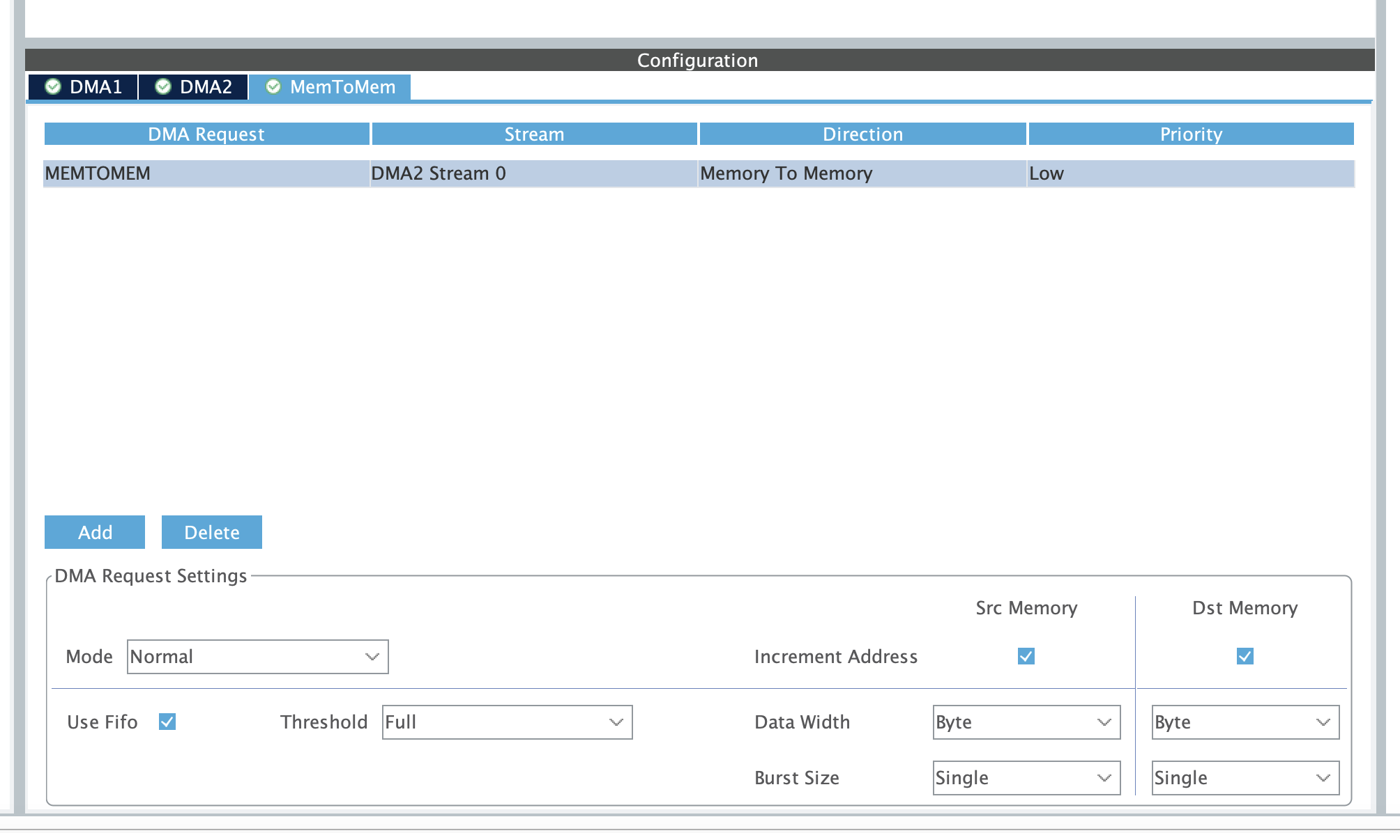
* Configure DMA for memory to memory transfers
* hdma_memtomem_dma2_stream0
*/
static void MX_DMA_Init(void)
{
/* DMA controller clock enable */
__HAL_RCC_DMA2_CLK_ENABLE();
/* Configure DMA request hdma_memtomem_dma2_stream0 on DMA2_Stream0 */
hdma_memtomem_dma2_stream0.Instance = DMA2_Stream0;
hdma_memtomem_dma2_stream0.Init.Channel = DMA_CHANNEL_0;
hdma_memtomem_dma2_stream0.Init.Direction = DMA_MEMORY_TO_MEMORY;
hdma_memtomem_dma2_stream0.Init.PeriphInc = DMA_PINC_ENABLE;
hdma_memtomem_dma2_stream0.Init.MemInc = DMA_MINC_ENABLE;
hdma_memtomem_dma2_stream0.Init.PeriphDataAlignment = DMA_PDATAALIGN_BYTE;
hdma_memtomem_dma2_stream0.Init.MemDataAlignment = DMA_MDATAALIGN_BYTE;
hdma_memtomem_dma2_stream0.Init.Mode = DMA_NORMAL;
hdma_memtomem_dma2_stream0.Init.Priority = DMA_PRIORITY_LOW;
hdma_memtomem_dma2_stream0.Init.FIFOMode = DMA_FIFOMODE_ENABLE;
hdma_memtomem_dma2_stream0.Init.FIFOThreshold = DMA_FIFO_THRESHOLD_FULL;
hdma_memtomem_dma2_stream0.Init.MemBurst = DMA_MBURST_SINGLE;
hdma_memtomem_dma2_stream0.Init.PeriphBurst = DMA_PBURST_SINGLE;
if (HAL_DMA_Init(&hdma_memtomem_dma2_stream0) != HAL_OK)
{
Error_Handler( );
}
/* DMA interrupt init */
/* DMA2_Stream0_IRQn interrupt configuration */
HAL_NVIC_SetPriority(DMA2_Stream0_IRQn, 0, 0);
HAL_NVIC_EnableIRQ(DMA2_Stream0_IRQn);
}
/* USER CODE BEGIN 4 */
void XferCpltCallback(DMA_HandleTypeDef *hdma)
{
__NOP(); //Line reached only if transfer was successful. Toggle a breakpoint here
}
/* USER CODE END 4 */
/**
* @brief This function is executed in case of error occurrence.
* @retval None
*/
void Error_Handler(void)
{
/* USER CODE BEGIN Error_Handler_Debug */
/* User can add his own implementation to report the HAL error return state */
__disable_irq();
while (1)
{
}
/* USER CODE END Error_Handler_Debug */
}
#ifdef USE_FULL_ASSERT
/**
* @brief Reports the name of the source file and the source line number
* where the assert_param error has occurred.
* @param file: pointer to the source file name
* @param line: assert_param error line source number
* @retval None
*/
void assert_failed(uint8_t *file, uint32_t line)
{
/* USER CODE BEGIN 6 */
/* User can add his own implementation to report the file name and line number,
ex: printf("Wrong parameters value: file %s on line %d\r\n", file, line) */
/* USER CODE END 6 */
}
#endif /* USE_FULL_ASSERT */
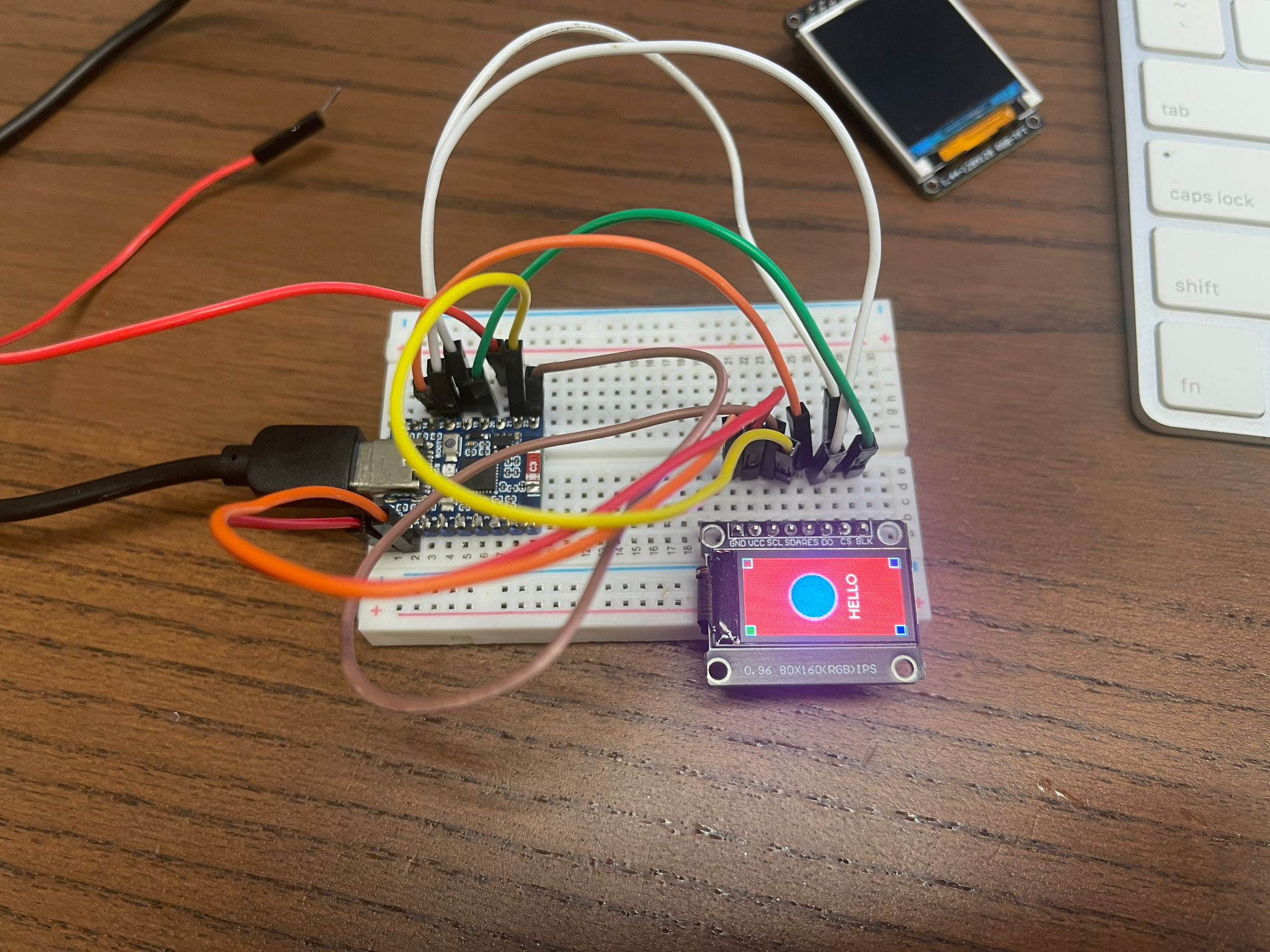
All device pins should be connected to the same pins on the ESP32 board except the CS (chip select) pin.
import lcd_bus
from micropython import const
import machine
from time import sleep
import st7735
import lvgl as lv
import utime as time
from fs_driver import fs_register
from machine import Pin
import AD9833
selected = 0
def drawMenu():
button1 = lv.button(scrn)
button1.set_pos(4, 30)
button1.set_size(40, 20)
label1 = lv.label(button1)
label1.set_text("Func")
label1.set_style_text_color(lv.color_hex(0x000000), 0) # Black text
label1.set_style_text_font(lv.font_montserrat_12, 0)
if selected == 0:
button1.set_style_bg_color(
lv.color_hex(0xffffff), 0)
label1.center()
button2 = lv.button(scrn)
button2.set_pos(50, 30)
button2.set_size(75, 20)
label2 = lv.label(button2)
label2.set_text("Multimeter")
label2.set_style_text_color(lv.color_hex(0x000000), 0) # Black text
label2.set_style_text_font(lv.font_montserrat_12, 0)
if selected == 1:
button2.set_style_bg_color(
lv.color_hex(0xffffff), 0)
label2.center()
# display settings
_WIDTH = 128
_HEIGHT = 128
_BL = 19
_RST = 14
_DC = 15
_MOSI = 21 # SDA
# _MISO = 20
_SCK = 22 # SCL
_HOST = 1 # SPI2
_LCD_CS = 18
_LCD_FREQ = 4000000
_OFFSET_X = 2
_OFFSET_Y = 3
print('s1')
spi_bus = machine.SPI.Bus(
host=_HOST,
mosi=_MOSI,
# miso=_MISO,
sck=_SCK
)
display_bus = lcd_bus.SPIBus(
spi_bus=spi_bus,
freq=_LCD_FREQ,
dc=_DC,
cs=_LCD_CS,
)
display = st7735.ST7735(
data_bus=display_bus,
display_width=_WIDTH,
display_height=_HEIGHT,
backlight_pin=_BL,
reset_pin=_RST,
reset_state=st7735.STATE_LOW,
backlight_on_state=st7735.STATE_HIGH,
color_space=lv.COLOR_FORMAT.RGB565,
color_byte_order=st7735.BYTE_ORDER_BGR,
rgb565_byte_swap=True,
offset_x=_OFFSET_X,
offset_y=_OFFSET_Y
)
print('s4')
# Initialize display
display.init(st7735.TYPE_R_RED)
display.set_rotation(lv.DISPLAY_ROTATION._180)
display.set_backlight(100)
# Create screen
scrn = lv.screen_active()
scrn.set_style_bg_color(lv.color_hex(0x000000), 0)
fs_drv = lv.fs_drv_t()
fs_register(fs_drv, "S")
img = lv.image(scrn)
img.set_src("S:colorful20.png")
img.set_size(20, 20)
img.set_pos(0, 5)
label = lv.label(scrn)
label.set_text("Multimeter")
label.set_pos(24, 8)
label.set_style_text_color(lv.color_hex(0xffffff), 0)
label.set_style_text_font(lv.font_montserrat_12, 0)
button0 = Pin(20, Pin.IN, Pin.PULL_UP) # Button pin
button1 = Pin(5, Pin.IN, Pin.PULL_UP) # Button pin
drawMenu()
# temp.value(1)
# display_bus.deinit()
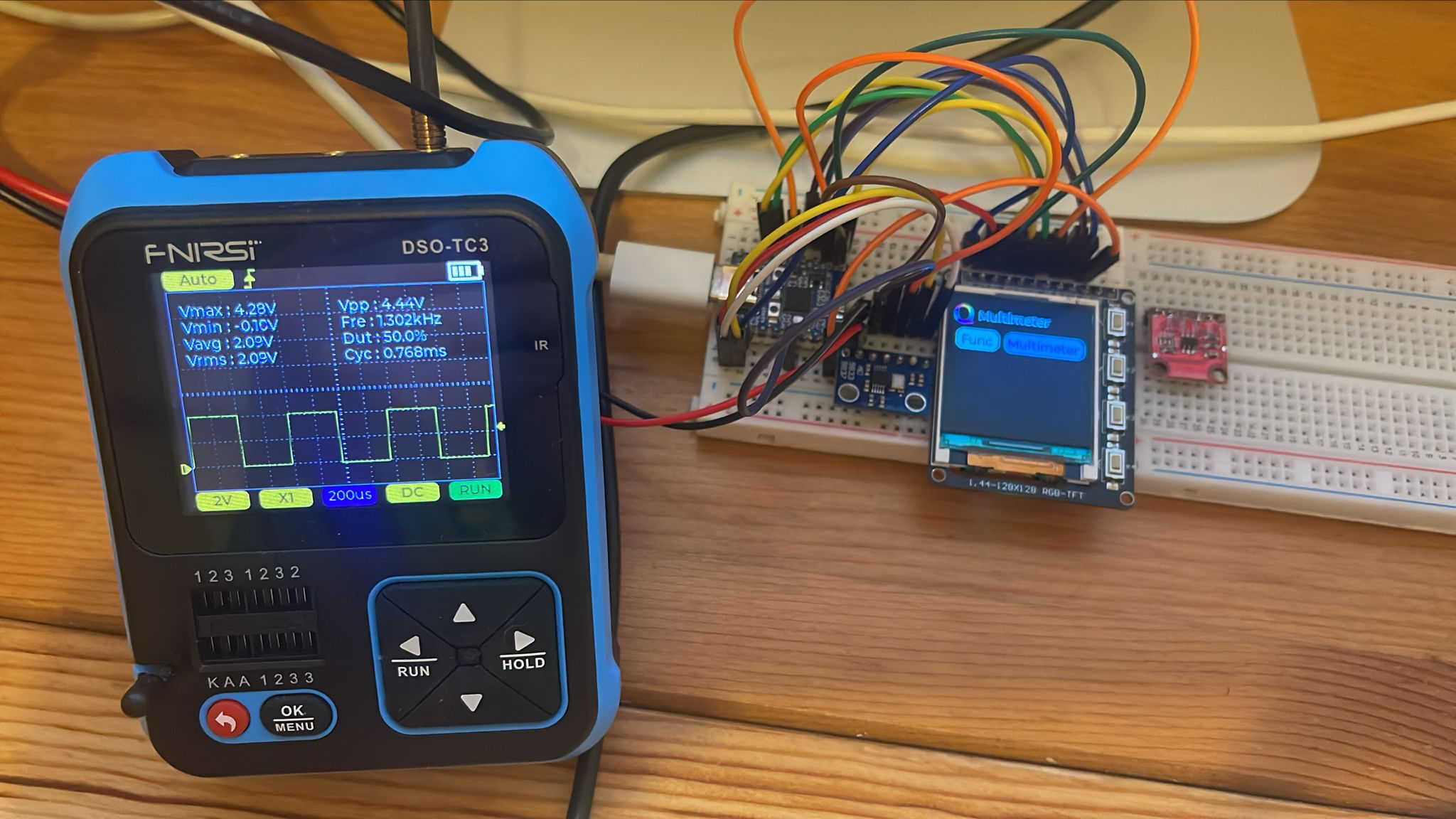
ad9833 = AD9833.AD9833(sdo = 21, clk = 22, cs = 2, fmclk = 25)
ad9833.set_frequency(1300, 0)
# ad9833.set_frequency(2600, 1)
ad9833.set_phase(0, 0, rads = False)
ad9833.set_phase(180, 1, rads = False)
time.sleep(0.5)
# ad9833.select_freq_phase(0,0)
# ad9833.set_mode('SIN')
# time.sleep(2)
ad9833.set_mode('SQUARE')
# ad9833.disable()
# time.sleep(2)
# temp.value(0)
# time.sleep(200)
print("end")
while True:
time.sleep_ms(20)
lv.task_handler()
sleep(0.2)
if not button0.value():
selected = (selected + 1) % 2
print(selected)
drawMenu()
lv.refr_now(lv.screen_active().get_display())
# ad9833.select_freq_phase(0,0)
ad9833.set_mode('SIN')
if not button1.value():
selected = (selected - 1) % 2
print(selected)
drawMenu()
lv.refr_now(lv.screen_active().get_display())
ad9833.set_frequency(9000, 0)
ad9833.set_mode('SQUARE/2')
Special Thanks to Mr kdschlosser for writing the driver
git clone https://github.com/lvgl-micropython/lvgl_micropython.git
cd lvgl_micropython
python3 make.py esp32 clean \
  --flash-size=4 \
  BOARD=ESP32_GENERIC_C6 \
  DISPLAY=jd9853 \
  INDEV=axs5106

esptool.py --chip esp32c6 \
     -b 460800 \
     --before default_reset \
     --after hard_reset \
     write_flash --flash_mode dio \
     --flash_size 4MB --flash_freq 40m \
     --erase-all 0x0 build/lvgl_micropy_ESP32_GENERIC_C6-4.bin
Example:
import lcd_bus
from micropython import const
import machine
from time import sleep
import jd9853
import lvgl as lv
lv.init()
# display settings
_WIDTH = 172
_HEIGHT = 320
_BL = 23
_RST = 22
_DC = 15
_MOSI = 2 #SDA
_MISO = 5
_SCK = 1 # SCL
_HOST = 1 # SPI2
_LCD_CS = 14
_LCD_FREQ = 2000000
_OFFSET_X = 34
_OFFSET_Y = 0
print('s1');
spi_bus = machine.SPI.Bus(
host=_HOST,
mosi=_MOSI,
#miso=_MISO,
sck=_SCK
)
print('s2');
display_bus = lcd_bus.SPIBus(
spi_bus=spi_bus,
freq=_LCD_FREQ,
dc=_DC,
cs=_LCD_CS,
)
print('s3');
display = jd9853.JD9853(
data_bus=display_bus,
display_width=_WIDTH,
display_height=_HEIGHT,
backlight_pin=_BL,
reset_pin=_RST,
reset_state=jd9853.STATE_LOW,
backlight_on_state=jd9853.STATE_HIGH,
color_space=lv.COLOR_FORMAT.RGB565,
color_byte_order=jd9853.BYTE_ORDER_BGR,
rgb565_byte_swap=True,
offset_x=_OFFSET_X,
offset_y=_OFFSET_Y
)
print('s4');
display.set_power(True)
display.init()
display.set_color_inversion(True)
# display.set_rotation(lv.DISPLAY_ROTATION._90)
display.set_backlight(100)
scrn = lv.screen_active()
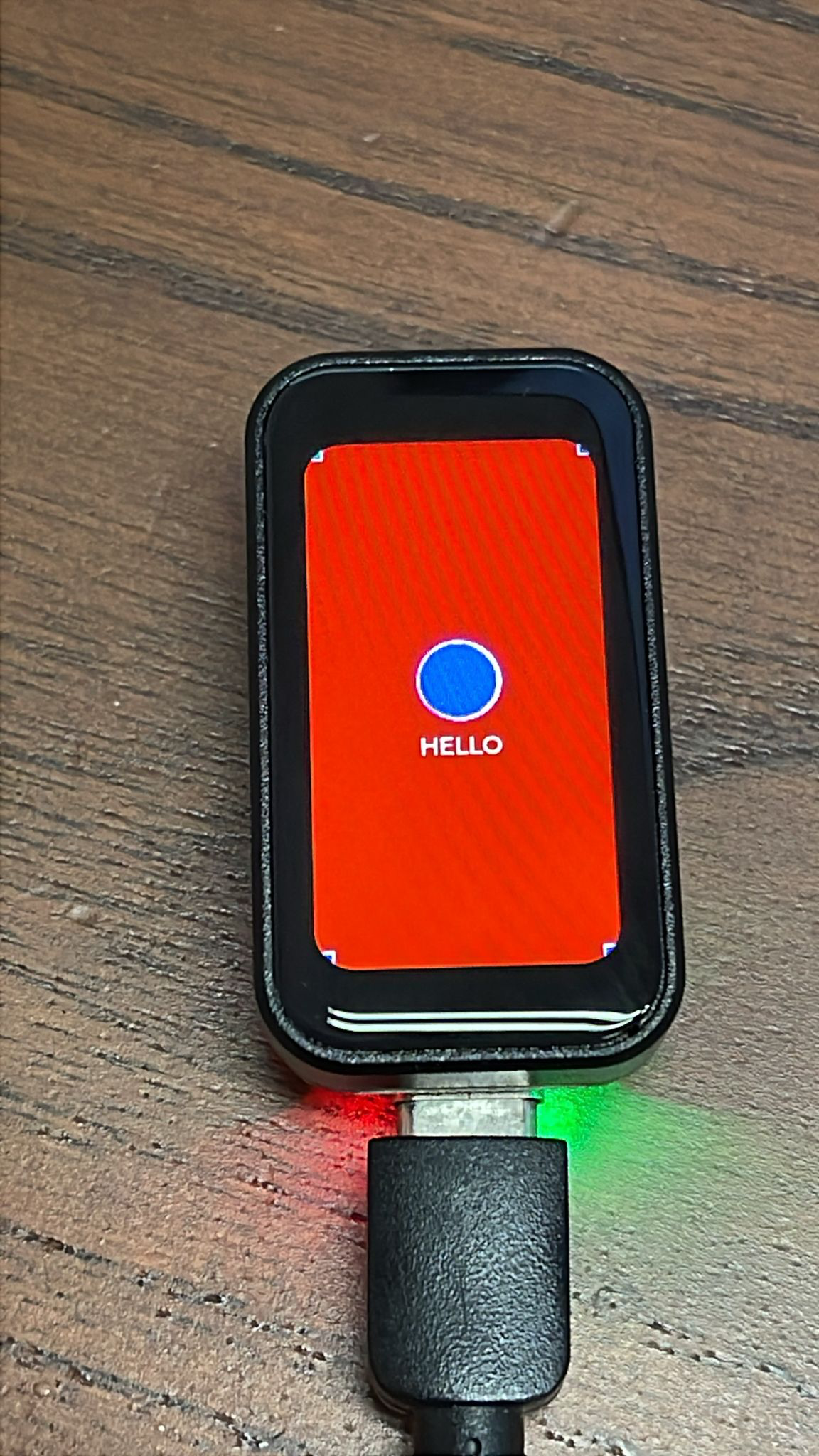
scrn.set_style_bg_color(lv.color_hex(0xff0000), 0)
label = lv.label(scrn)
label.set_text('HELLO')
label.set_style_text_color(lv.color_hex(0xffffff), 0)
label.align(lv.ALIGN.CENTER, 0, 30)
# Draw a rectangle
rect1 = lv.obj(scrn)
rect1.set_size(10, 10)
rect1.set_style_bg_color(lv.color_hex(0x00aa00), 0)
rect1.set_style_border_color(lv.color_hex(0xffffff), 0)
rect1.set_style_border_width(1, 0)
rect1.set_style_radius(0, 0)
rect1.align(lv.ALIGN.TOP_LEFT, 0, 0)
rect2 = lv.obj(scrn)
rect2.set_size(10, 10)
rect2.set_style_bg_color(lv.color_hex(0xaa0000), 0)
rect2.set_style_border_color(lv.color_hex(0xffffff), 0)
rect2.set_style_border_width(1, 0)
rect2.set_style_radius(0, 0)
rect2.align(lv.ALIGN.TOP_RIGHT, 0, 0)
rect3 = lv.obj(scrn)
rect3.set_size(10, 10)
rect3.set_style_bg_color(lv.color_hex(0xaa00aa), 0)
rect3.set_style_border_color(lv.color_hex(0xffffff), 0)
rect3.set_style_border_width(1, 0)
rect3.set_style_radius(0, 0)
rect3.align(lv.ALIGN.BOTTOM_RIGHT, 0, 0)
rect4 = lv.obj(scrn)
rect4.set_size(10, 10)
rect4.set_style_bg_color(lv.color_hex(0x0000aa), 0)
rect4.set_style_border_color(lv.color_hex(0xffffff), 0)
rect4.set_style_border_width(1, 0)
rect4.set_style_radius(0, 0)
rect4.align(lv.ALIGN.BOTTOM_LEFT, 0, 0)
# Draw a circle
circle = lv.obj(scrn)
circle.set_size(50, 50)
circle.set_style_bg_color(lv.color_hex(0x0000ff), 0)
circle.set_style_border_color(lv.color_hex(0xff00ff), 0)
circle.set_style_border_width(3, lv.STATE.DEFAULT)
circle.set_style_radius(25, 0) # Make it circular (radius = half of width/height)
circle.align(lv.ALIGN.CENTER, 0, -10)
print('end')
import utime as time
time_passed = 1000
while True:
start_time = time.ticks_ms()
time.sleep_ms(1) # sleep for 1 ms
lv.tick_inc(time_passed)
lv.task_handler()
end_time = time.ticks_ms()
time_passed = time.ticks_diff(end_time, start_time)
More Examples on https://github.com/quantrpeter/Waveshare-ESP32-C6-1.47-Touch-Micropython-LVGL
import lcd_bus
from micropython import const
import machine
from time import sleep
import st7735
import lvgl as lv
lv.init()
# display settings
_WIDTH = 128
_HEIGHT = 128
_BL = 19
_RST = 14
_DC = 15
_MOSI = 21 #SDA
_MISO = 20
_SCK = 22 # SCL
_HOST = 1 # SPI2
_LCD_CS = 18
_LCD_FREQ = 2000000
_OFFSET_X = 2
_OFFSET_Y = 3
print('s1');
spi_bus = machine.SPI.Bus(
host=_HOST,
mosi=_MOSI,
#miso=_MISO,
sck=_SCK
)
print('s2');
display_bus = lcd_bus.SPIBus(
spi_bus=spi_bus,
freq=_LCD_FREQ,
dc=_DC,
cs=_LCD_CS,
)
print('s3');
display = st7735.ST7735(
data_bus=display_bus,
display_width=_WIDTH,
display_height=_HEIGHT,
backlight_pin=_BL,
reset_pin=_RST,
reset_state=st7735.STATE_LOW,
backlight_on_state=st7735.STATE_HIGH,
color_space=lv.COLOR_FORMAT.RGB565,
color_byte_order=st7735.BYTE_ORDER_BGR,
rgb565_byte_swap=True,
offset_x=_OFFSET_X,
offset_y=_OFFSET_Y
)
print('s4');
# display.set_power(True)
display.init(st7735.TYPE_R_RED)
display.set_rotation(lv.DISPLAY_ROTATION._180)
display.set_backlight(100)
scrn = lv.screen_active()
scrn.set_style_bg_color(lv.color_hex(0xff0000), 0)
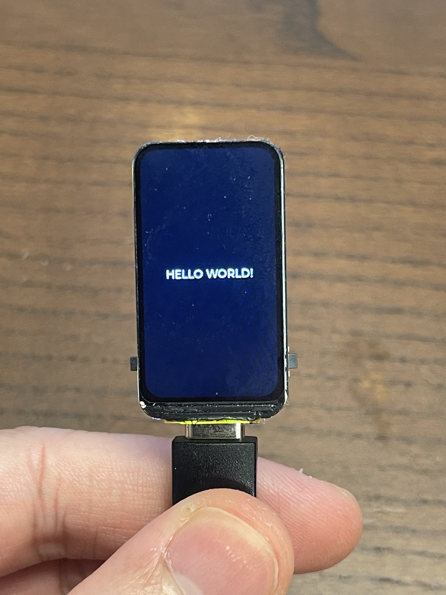
label = lv.label(scrn)
label.set_text('HELLO WORLD!')
label.set_style_text_color(lv.color_hex(0xffffff), 0)
label.align(lv.ALIGN.CENTER, 0, 30)
# Draw a rectangle
rect1 = lv.obj(scrn)
rect1.set_size(10, 10)
rect1.set_style_bg_color(lv.color_hex(0x00aa00), 0)
rect1.set_style_border_color(lv.color_hex(0xffffff), 0)
rect1.set_style_border_width(1, 0)
rect1.set_style_radius(0, 0)
rect1.align(lv.ALIGN.TOP_LEFT, 0, 0)
rect2 = lv.obj(scrn)
rect2.set_size(10, 10)
rect2.set_style_bg_color(lv.color_hex(0xaa0000), 0)
rect2.set_style_border_color(lv.color_hex(0xffffff), 0)
rect2.set_style_border_width(1, 0)
rect2.set_style_radius(0, 0)
rect2.align(lv.ALIGN.TOP_RIGHT, 0, 0)
rect3 = lv.obj(scrn)
rect3.set_size(10, 10)
rect3.set_style_bg_color(lv.color_hex(0xaa00aa), 0)
rect3.set_style_border_color(lv.color_hex(0xffffff), 0)
rect3.set_style_border_width(1, 0)
rect3.set_style_radius(0, 0)
rect3.align(lv.ALIGN.BOTTOM_RIGHT, 0, 0)
rect4 = lv.obj(scrn)
rect4.set_size(10, 10)
rect4.set_style_bg_color(lv.color_hex(0x0000aa), 0)
rect4.set_style_border_color(lv.color_hex(0xffffff), 0)
rect4.set_style_border_width(1, 0)
rect4.set_style_radius(0, 0)
rect4.align(lv.ALIGN.BOTTOM_LEFT, 0, 0)
# Draw a circle
circle = lv.obj(scrn)
circle.set_size(50, 50)
circle.set_style_bg_color(lv.color_hex(0x0000ff), 0)
circle.set_style_border_color(lv.color_hex(0xff00ff), 0)
circle.set_style_border_width(3, lv.STATE.DEFAULT)
circle.set_style_radius(25, 0) # Make it circular (radius = half of width/height)
circle.align(lv.ALIGN.CENTER, 0, -10)
print('end')
import utime as time
time_passed = 1000
while True:
start_time = time.ticks_ms()
time.sleep_ms(1) # sleep for 1 ms
lv.tick_inc(time_passed)
lv.task_handler()
end_time = time.ticks_ms()
time_passed = time.ticks_diff(end_time, start_time)
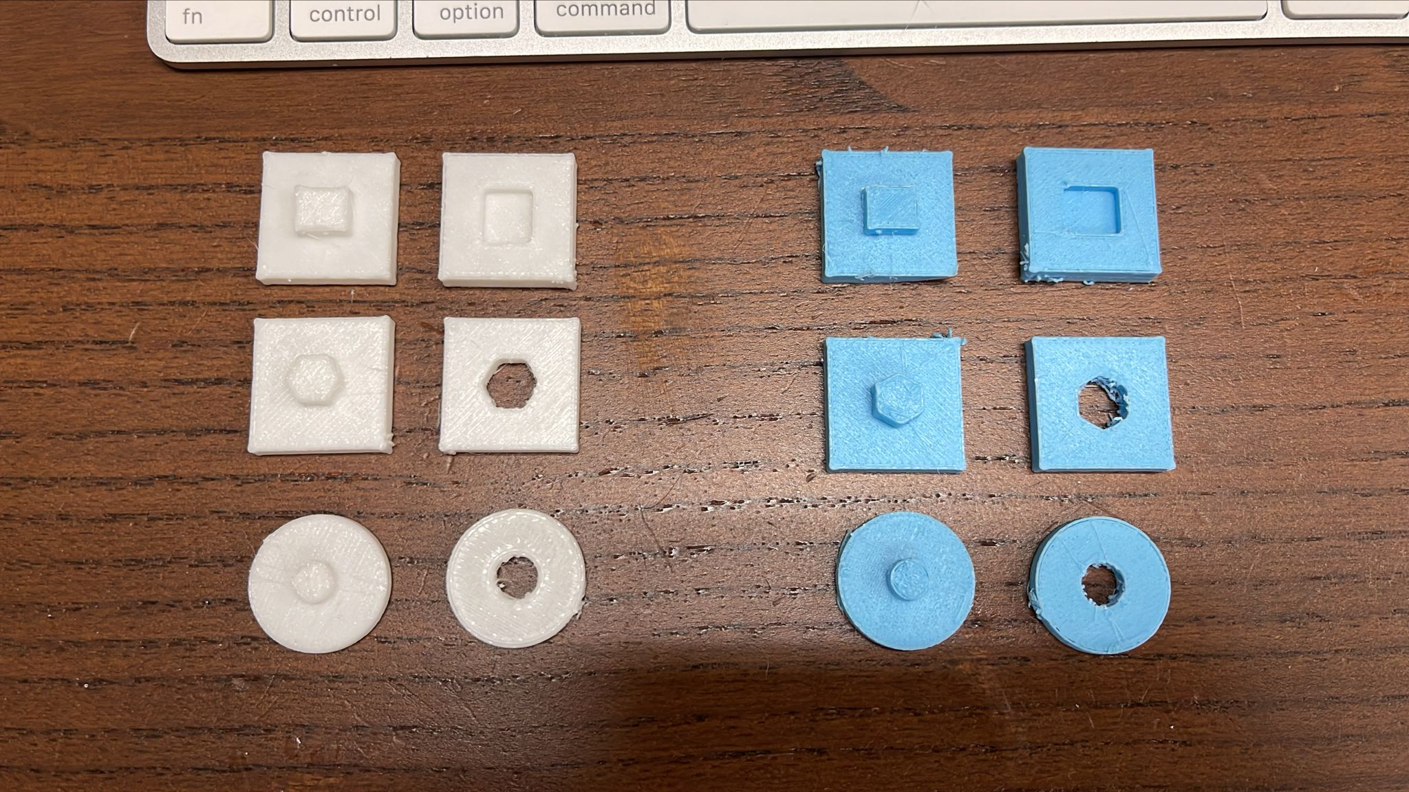
My old Ender 3 Pro, give 0.3mm X-Y Hole compensation, now no need polishing, I can plug them into another. Two filament print from two different nozzle temperature, same perfect.


https://www.waveshare.com/wiki/ESP32-C6-Zero
git clone https://github.com/lvgl-micropython/lvgl_micropython.git
cd lvgl_micropython
python3 make.py esp32 clean \
  --flash-size=4 \
  BOARD=ESP32_GENERIC_C6 \
  DISPLAY=ST7735
esptool.py --chip esp32c6 \
    -b 460800 \
    --before default_reset \
    --after hard_reset write_flash \
    --flash_mode dio \
    --flash_size 4MB \
    --flash_freq 80m \
    --erase-all 0x0 build/lvgl_micropy_ESP32_GENERIC_C6-4.bin
import lcd_bus
from micropython import const
import machine
from time import sleep
import st7735
import lvgl as lv

lv.init()

# display settings
_WIDTH = 128
_HEIGHT = 128
_BL = 19
_RST = 14
_DC = 15

_MOSI = 21 #SDA
_MISO = 20
_SCK = 22  # SCL
_HOST = 1  # SPI2

_LCD_CS = 18
_LCD_FREQ = 2000000

_OFFSET_X = 2
_OFFSET_Y = 3

print('s1');
spi_bus = machine.SPI.Bus(
    host=_HOST,
    mosi=_MOSI,
    #miso=_MISO,
    sck=_SCK
)

print('s2');
display_bus = lcd_bus.SPIBus(
    spi_bus=spi_bus,
    freq=_LCD_FREQ,
    dc=_DC,
    cs=_LCD_CS,
)

print('s3');
display = st7735.ST7735(
    data_bus=display_bus,
    display_width=_WIDTH,
    display_height=_HEIGHT,
    backlight_pin=_BL,
    reset_pin=_RST,
    reset_state=st7735.STATE_LOW,
    backlight_on_state=st7735.STATE_HIGH,
    color_space=lv.COLOR_FORMAT.RGB565,
    color_byte_order=st7735.BYTE_ORDER_BGR,
    rgb565_byte_swap=True,
    offset_x=_OFFSET_X,
    offset_y=_OFFSET_Y
)

print('s4');

# display.set_power(True)
display.init(st7735.TYPE_R_RED)
display.set_rotation(lv.DISPLAY_ROTATION._180)
display.set_backlight(100)

scrn = lv.screen_active()
scrn.set_style_bg_color(lv.color_hex(0xff0000), 0)

label = lv.label(scrn)
label.set_text('HELLO WORLD!')
label.set_style_text_color(lv.color_hex(0xffffff), 0)
label.align(lv.ALIGN.CENTER, 0, 30)

# Draw a rectangle
rect1 = lv.obj(scrn)
rect1.set_size(10, 10)
rect1.set_style_bg_color(lv.color_hex(0x00aa00), 0)  # Green color
rect1.set_style_border_color(lv.color_hex(0xffffff), 0)  # Yellow border
rect1.set_style_border_width(1, 0)
rect1.set_style_radius(0, 0)
rect1.align(lv.ALIGN.TOP_LEFT, 0, 0)

rect2 = lv.obj(scrn)
rect2.set_size(10, 10)
rect2.set_style_bg_color(lv.color_hex(0xaa0000), 0)  # Green color
rect2.set_style_border_color(lv.color_hex(0xffffff), 0)  # Yellow border
rect2.set_style_border_width(1, 0)
rect2.set_style_radius(0, 0)
rect2.align(lv.ALIGN.TOP_RIGHT, 0, 0)

rect3 = lv.obj(scrn)
rect3.set_size(10, 10)
rect3.set_style_bg_color(lv.color_hex(0xaa00aa), 0)  # Green color
rect3.set_style_border_color(lv.color_hex(0xffffff), 0)  # Yellow border
rect3.set_style_border_width(1, 0)
rect3.set_style_radius(0, 0)
rect3.align(lv.ALIGN.BOTTOM_RIGHT, 0, 0)

rect4 = lv.obj(scrn)
rect4.set_size(10, 10)
rect4.set_style_bg_color(lv.color_hex(0x0000aa), 0)  # Green color
rect4.set_style_border_color(lv.color_hex(0xffffff), 0)  # Yellow border
rect4.set_style_border_width(1, 0)
rect4.set_style_radius(0, 0)
rect4.align(lv.ALIGN.BOTTOM_LEFT, 0, 0)

# Draw a circle
circle = lv.obj(scrn)
circle.set_size(50, 50)
circle.set_style_bg_color(lv.color_hex(0x0000ff), 0)  # Blue color
circle.set_style_border_color(lv.color_hex(0xff00ff), 0)  # Magenta border
circle.set_style_border_width(3, lv.STATE.DEFAULT)
circle.set_style_radius(25, 0)  # Make it circular (radius = half of width/height)
circle.align(lv.ALIGN.CENTER, 0, -10)

print('end')

import utime as time
time_passed = 1000

while True:
    start_time = time.ticks_ms()
    time.sleep_ms(1)  # sleep for 1 ms
    lv.tick_inc(time_passed)
    lv.task_handler()
    end_time = time.ticks_ms()
    time_passed = time.ticks_diff(end_time, start_time)
git clone https://github.com/lvgl-micropython/lvgl_micropython.git
cd lvgl_micropython
python3 make.py esp32 clean \
  --flash-size=4 \
  BOARD=ESP32_GENERIC \
  DISPLAY=ili9341 \
  INDEV=xpt2046

esptool.py --chip esp32 \
     -b 460800 \
     --before default_reset \
     --after hard_reset \
     write_flash --flash_mode dio \
     --flash_size 4MB --flash_freq 40m \
     --erase-all 0x0 build/lvgl_micropy_ESP32_GENERIC-4.bin

import lcd_bus
from micropython import const
import machine
# display settings
_WIDTH = const(240)
_HEIGHT = const(320)
_BL = const(21)
_RST = const(17)
_DC = const(2)
_MOSI = const(13)
#_MISO = const(12)
_SCK = const(14)
_HOST = const(1) # SPI2
_LCD_CS = const(15)
_LCD_FREQ = const(40000000)
#_TOUCH_CS = const(9)
#_TOUCH_FREQ = const(1000000)
spi_bus = machine.SPI.Bus(
host=_HOST,
mosi=_MOSI,
#miso=_MISO,
sck=_SCK
)
display_bus = lcd_bus.SPIBus(
spi_bus=spi_bus,
freq=_LCD_FREQ,
dc=_DC,
cs=_LCD_CS,
)
import ili9341 # NOQA
import lvgl as lv # NOQA
display = ili9341.ILI9341(
data_bus=display_bus,
display_width=_WIDTH,
display_height=_HEIGHT,
reset_pin=_RST,
reset_state=ili9341.STATE_LOW,
backlight_pin=_BL,
backlight_on_state=ili9341.STATE_HIGH,
color_space=lv.COLOR_FORMAT.RGB565,
color_byte_order=ili9341.BYTE_ORDER_BGR,
rgb565_byte_swap=True,
)
import task_handler # NOQA
import xpt2046 # NOQA
display.set_power(True)
display.init(1)
# display.set_color_inversion(True)
display.set_rotation(lv.DISPLAY_ROTATION._90)
display.set_backlight(100)
#touch_dev = machine.SPI.Device(
# spi_bus=spi_bus,
# freq=_TOUCH_FREQ,
# cs=_TOUCH_CS
#)
#indev = xpt2046.XPT2046(touch_dev,debug=False,startup_rotation=lv.DISPLAY_ROTATION._0)
#indev.calibrate()
th = task_handler.TaskHandler()
scrn = lv.screen_active()
#scrn.set_style_bg_color(lv.color_hex(0xFFFFFF), 0)
#btnm = lv.buttonmatrix(scrn)
#btnm.add_event_cb(lambda e: btnm_event_handler(e,scrn),lv.EVENT.VALUE_CHANGED, None)
#btnm.set_size(230,120)
#btnm.align(1,5,5)
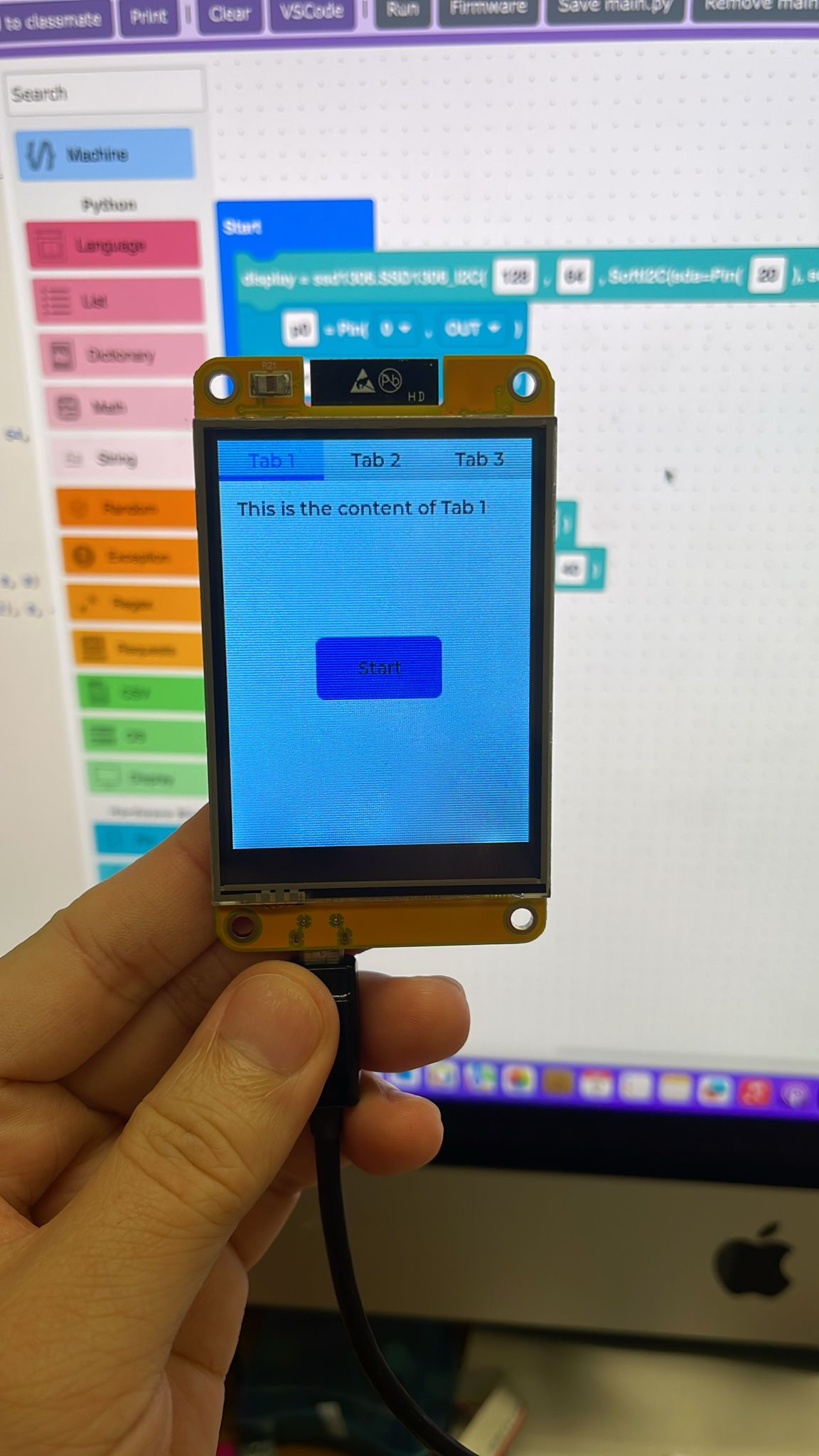
tabview = lv.tabview(scrn)
tabview.set_tab_bar_size(30)
tab1 = tabview.add_tab("Tab 1")
tab2 = tabview.add_tab("Tab 2")
tab3 = tabview.add_tab("Tab 3")
# Add content to the tabs
label1 = lv.label(tab1)
label1.set_text("This is the content of Tab 1")
#label2 = lv.label(tab2)
#label2.set_text("This is the content of Tab 2")
label3 = lv.label(tab3)
label3.set_text("This is the content of Tab 3")
btn = lv.button(tab1)
btn.center()
btn.set_size(100,50)
btn.set_style_bg_color(lv.color_make(255, 0, 0), 0) # RGB: Red=255, Green=0, Blue=0
lbl = lv.label(btn)
lbl.set_text('Start')
lbl.center()
# Add second button
btn2 = lv.button(tab1)
btn2.set_size(100,50)
btn2.align(lv.ALIGN.CENTER, 0, 60) # Position below the first button
lbl2 = lv.label(btn2)
lbl2.set_text('Stop')
lbl2.center()
tab2.set_flex_flow(lv.FLEX_FLOW.COLUMN)
lab21 = lv.label(tab2)
lab21.set_text('Group 1')
chk21 = lv.checkbox(tab2)
chk21.set_text('Option 1')
chk22 = lv.checkbox(tab2)
chk22.set_text('Option 2')
chk23 = lv.checkbox(tab2)
chk23.set_text('Option 3')
chk24 = lv.checkbox(tab2)
chk24.set_text('Option 4')
lab22 = lv.label(tab2)
lab22.set_text('Group 2')
chk25 = lv.checkbox(tab2)
chk25.set_text('Option 5')
chk26 = lv.checkbox(tab2)
chk26.set_text('Option 6')
chk27 = lv.checkbox(tab2)
chk27.set_text('Option 7')
chk28 = lv.checkbox(tab2)
chk28.set_text('Option 8')
o = 1
def btnm_event_handler(e,ta):
global o
obj = e.get_target()
o=obj
print("Toggled")
Example: Clock

import lcd_bus
from micropython import const
import machine
import time  # Add time module for clock functionality

# Try to import ntptime for NTP sync
try:
    import ntptime
    NTP_AVAILABLE = True
except ImportError:
    NTP_AVAILABLE = False
    print("ntptime not available")

# Try to import network for WiFi
try:
    import network
    NETWORK_AVAILABLE = True
except ImportError:
    NETWORK_AVAILABLE = False
    print("network not available")

# WiFi Configuration - CHANGE THESE TO YOUR WIFI CREDENTIALS
WIFI_SSID = "Quantr 2.4G"        # Replace with your WiFi name
WIFI_PASSWORD = "quantrwi"  # Replace with your WiFi password

# Timezone Configuration
TIMEZONE_OFFSET = 8  # Hong Kong is UTC+8 hours
TIMEZONE_NAME = "Hong Kong"


# display settings
_WIDTH = const(240)
_HEIGHT = const(320)
_BL = const(21)
_RST = const(17)
_DC = const(2)

_MOSI = const(13)
#_MISO = const(12)
_SCK = const(14)
_HOST = const(1)  # SPI2

_LCD_CS = const(15)
_LCD_FREQ = const(40000000)

#_TOUCH_CS = const(9)
#_TOUCH_FREQ = const(1000000)

spi_bus = machine.SPI.Bus(
    host=_HOST,
    mosi=_MOSI,
    #miso=_MISO,
    sck=_SCK
)

display_bus = lcd_bus.SPIBus(
    spi_bus=spi_bus,
    freq=_LCD_FREQ,
    dc=_DC,
    cs=_LCD_CS,
)


import ili9341  # NOQA
import lvgl as lv  # NOQA


display = ili9341.ILI9341(
    data_bus=display_bus,
    display_width=_WIDTH,
    display_height=_HEIGHT,
     reset_pin=_RST,
    reset_state=ili9341.STATE_LOW,
    backlight_pin=_BL,
    backlight_on_state=ili9341.STATE_HIGH,
    color_space=lv.COLOR_FORMAT.RGB565,
    color_byte_order=ili9341.BYTE_ORDER_BGR,
    rgb565_byte_swap=True,
)

import task_handler  # NOQA
import xpt2046  # NOQA

display.set_power(True)
display.init(1)
# display.set_color_inversion(True)
display.set_rotation(lv.DISPLAY_ROTATION._90)
display.set_backlight(100)

#touch_dev = machine.SPI.Device(
#    spi_bus=spi_bus,
#    freq=_TOUCH_FREQ,
#    cs=_TOUCH_CS
#)

#indev = xpt2046.XPT2046(touch_dev,debug=False,startup_rotation=lv.DISPLAY_ROTATION._0)

#indev.calibrate()

th = task_handler.TaskHandler()

# WiFi connection functions
def connect_wifi():
    """Connect to WiFi network"""
    if not NETWORK_AVAILABLE:
        print("Network module not available")
        return False

    try:
        wlan = network.WLAN(network.STA_IF)
        wlan.active(True)

        if wlan.isconnected():
            print("WiFi already connected")
            print(f"IP address: {wlan.ifconfig()[0]}")
            return True

        print(f"Connecting to WiFi: {WIFI_SSID}")
        wlan.connect(WIFI_SSID, WIFI_PASSWORD)

        # Wait for connection with timeout
        timeout = 10  # 10 seconds timeout
        while not wlan.isconnected() and timeout > 0:
            time.sleep(1)
            timeout -= 1
            print(".", end="")

        if wlan.isconnected():
            print(f"\nWiFi connected successfully!")
            print(f"IP address: {wlan.ifconfig()[0]}")
            return True
        else:
            print(f"\nWiFi connection failed!")
            return False

    except Exception as e:
        print(f"WiFi connection error: {e}")
        return False

def disconnect_wifi():
    """Disconnect from WiFi"""
    if not NETWORK_AVAILABLE:
        return

    try:
        wlan = network.WLAN(network.STA_IF)
        wlan.disconnect()
        wlan.active(False)
        print("WiFi disconnected")
    except Exception as e:
        print(f"WiFi disconnect error: {e}")

# Time setting functions
def get_local_time():
    """Get time adjusted for Hong Kong timezone (UTC+8)"""
    # Get UTC time
    utc_time = time.time()
    # Add timezone offset (8 hours = 8 * 3600 seconds)
    local_timestamp = utc_time + (TIMEZONE_OFFSET * 3600)
    # Convert to local time structure
    return time.localtime(local_timestamp)

def sync_time_ntp():
    """Try to sync time with NTP server (requires WiFi)"""
    if not NTP_AVAILABLE:
        print("NTP not available")
        return False

    if not NETWORK_AVAILABLE:
        print("Network not available")
        return False

    try:
        # Check if WiFi is connected
        wlan = network.WLAN(network.STA_IF)
        if wlan.isconnected():
            print("Syncing time with NTP server...")
            ntptime.settime()
            print(f"Time synced successfully! (UTC time will be converted to {TIMEZONE_NAME})")
            return True
        else:
            print("WiFi not connected, cannot sync NTP time")
            return False
    except Exception as e:
        print(f"NTP sync failed: {e}")
        return False

def set_manual_time():
    """Set time manually - modify the values as needed"""
    # Format: (year, month, day, weekday, hour, minute, second, microsecond)
    rtc = machine.RTC()
    # Set to July 4, 2025, 14:30:00 Hong Kong time
    # Note: This sets the RTC to UTC time, but we'll display Hong Kong time
    # So if we want to display 14:30 HK time, we set RTC to 06:30 UTC
    utc_hour = 14 - TIMEZONE_OFFSET  # Convert HK time to UTC
    if utc_hour < 0:
        utc_hour += 24
    rtc.datetime((2025, 7, 4, 5, utc_hour, 30, 0, 0))
    print(f"Manual time set to: 2025-07-04 14:30:00 {TIMEZONE_NAME} time")

def setup_time():
    """Setup the system time"""
    print("Setting up time...")

    # First try to connect to WiFi
    if connect_wifi():
        # If WiFi connected, try NTP sync
        if sync_time_ntp():
            print(f"Time setup complete via NTP (displaying {TIMEZONE_NAME} time)")
            return

    # If WiFi or NTP failed, use manual time
    print("Using manual time setting")
    set_manual_time()

    # Print current time to verify (Hong Kong time)
    current = get_local_time()
    print(f"Current {TIMEZONE_NAME} time: {current[0]}-{current[1]:02d}-{current[2]:02d} {current[3]:02d}:{current[4]:02d}:{current[5]:02d}")

# Initialize time
setup_time()

scrn = lv.screen_active()
scrn.set_style_bg_color(lv.color_hex(0xFFFFFF), 0)  # White background

#btnm = lv.buttonmatrix(scrn)
#btnm.add_event_cb(lambda e: btnm_event_handler(e,scrn),lv.EVENT.VALUE_CHANGED, None)
#btnm.set_size(230,120)
#btnm.align(1,5,5)

# SemiBlock label at the top
semiblock_label = lv.label(scrn)
semiblock_label.set_text("SemiBlock")
semiblock_label.align(lv.ALIGN.TOP_MID, -45, 20)
semiblock_label.set_style_text_color(lv.color_hex(0xFF80C0), 0)  # Pinkly blue color
semiblock_label.set_style_transform_scale(600, 0)  # Scale text to 200% (2x bigger)

# Digital clock display - large font
clock_label = lv.label(scrn)
clock_label.set_text("00:00:00")
clock_label.align(lv.ALIGN.LEFT_MID, 50, -15)
clock_label.set_style_transform_scale(500, 0)  # Scale text to 300% (3x bigger)
clock_label.set_style_text_color(lv.color_hex(0x000000), 0)  # Black color

# Date display
date_label = lv.label(scrn)
date_label.set_text("2025-01-01")
date_label.align(lv.ALIGN.LEFT_MID, 50, 30)
date_label.set_style_transform_scale(500, 0)
date_label.set_style_text_color(lv.color_hex(0x0000FF), 0)  # Blue color

# Day of week display
day_label = lv.label(scrn)
day_label.set_text("Monday")
day_label.align(lv.ALIGN.LEFT_MID, 50, 75)
day_label.set_style_transform_scale(500, 0)
day_label.set_style_text_color(lv.color_hex(0x0000FF), 0)  # Blue color

# Clock frame/border
clock_frame = lv.obj(scrn)
clock_frame.set_size(280, 140)
clock_frame.align(lv.ALIGN.CENTER, 0, 40)
clock_frame.set_style_border_width(2, 0)
clock_frame.set_style_border_color(lv.color_hex(0xFF80C0), 0)  # Gray border
clock_frame.set_style_bg_opa(lv.OPA.TRANSP, 0)  # Transparent background
clock_frame.set_style_radius(10, 0)  # Rounded corners

# Don't move labels to frame - keep them on main screen for proper updates
# Don't move labels to frame - keep them on main screen for proper updates

def update_clock():
    """Update the clock display with current time in Hong Kong timezone"""
    # Use Hong Kong local time instead of system time
    current_time = get_local_time()

    # Format time as HH:MM:SS
    time_str = "{:02d}:{:02d}:{:02d}".format(
        current_time[3],  # hour
        current_time[4],  # minute
        current_time[5]   # second
    )

    # Format date as YYYY-MM-DD
    date_str = "{:04d}-{:02d}-{:02d}".format(
        current_time[0],  # year
        current_time[1],  # month
        current_time[2]   # day
    )

    # Get day of week
    days = ["Monday", "Tuesday", "Wednesday", "Thursday", "Friday", "Saturday", "Sunday"]
    day_str = days[current_time[6]]

    clock_label.set_text(time_str)
    date_label.set_text(date_str)
    day_label.set_text(day_str)

    # Debug print to verify time is being read correctly
    print(f"{TIMEZONE_NAME} Time: {time_str}, Date: {date_str}, Day: {day_str}")

# Create a timer to update the clock every second
clock_timer = lv.timer_create(lambda timer: update_clock(), 1000, None)

# Initial clock update
update_clock()
Cheap Yellow Display Pins
Connector types
| Connector | Type | Note |
|---|---|---|
| P1 | 4P 1.25mm JST | Serial |
| P3 | 4P 1.25mm JST | GPIO |
| P4 | 2P 1.25mm JST | Speaker |
| CN1 | 4P 1.25mm JST | GPIO (I2C) |
What pins are available on the CYD?
There are 3 easily accessible GPIO pins
| Pin | Location | Note |
|---|---|---|
| IO35 | P3 JST connector | Input only pin, no internal pull-ups available |
| IO22 | P3 and CN1 JST connector | |
| IO27 | CN1 JST connector |
If you need more than that, you need to start taking them from something else. An SD Card sniffer like mentioned in the Add-ons is probably the next easiest.
After that you're probably de-soldering something!
Broken Out Pins
There are three 4P 1.25mm JST connectors on the board
P3
| Pin | Use | Note |
|---|---|---|
| GND | ||
| IO35 | Input only pin, no internal pull-ups available | |
| IO22 | Also on the CN1 connector | |
| IO21 | Used for the TFT Backlight, so not really usable |
CN1
This is a great candidate for I2C devices
| Pin | Use | Note |
|---|---|---|
| GND | ||
| IO22 | Also on P3 connector | |
| IO27 | ||
| 3.3V |
P1
| Pin | Use | Note |
|---|---|---|
| VIN | ||
| IO1(?) | TX | Maybe possible to use as a GPIO? |
| IO3(?) | RX | Maybe possible to use as a GPIO? |
| GND |
Buttons
The CYD has two buttons, reset and boot.
| Pin | Use | Note |
|---|---|---|
| IO0 | BOOT | Can be used as an input in sketches |
Speaker
The speaker connector is a 2P 1.25mm JST connector that is connected to the amplifier, so not usable as GPIO at the speaker connector
| Pin | Use | Note |
|---|---|---|
| IO26 | Connected to amp | i2s_set_dac_mode(I2S_DAC_CHANNEL_LEFT_EN); |
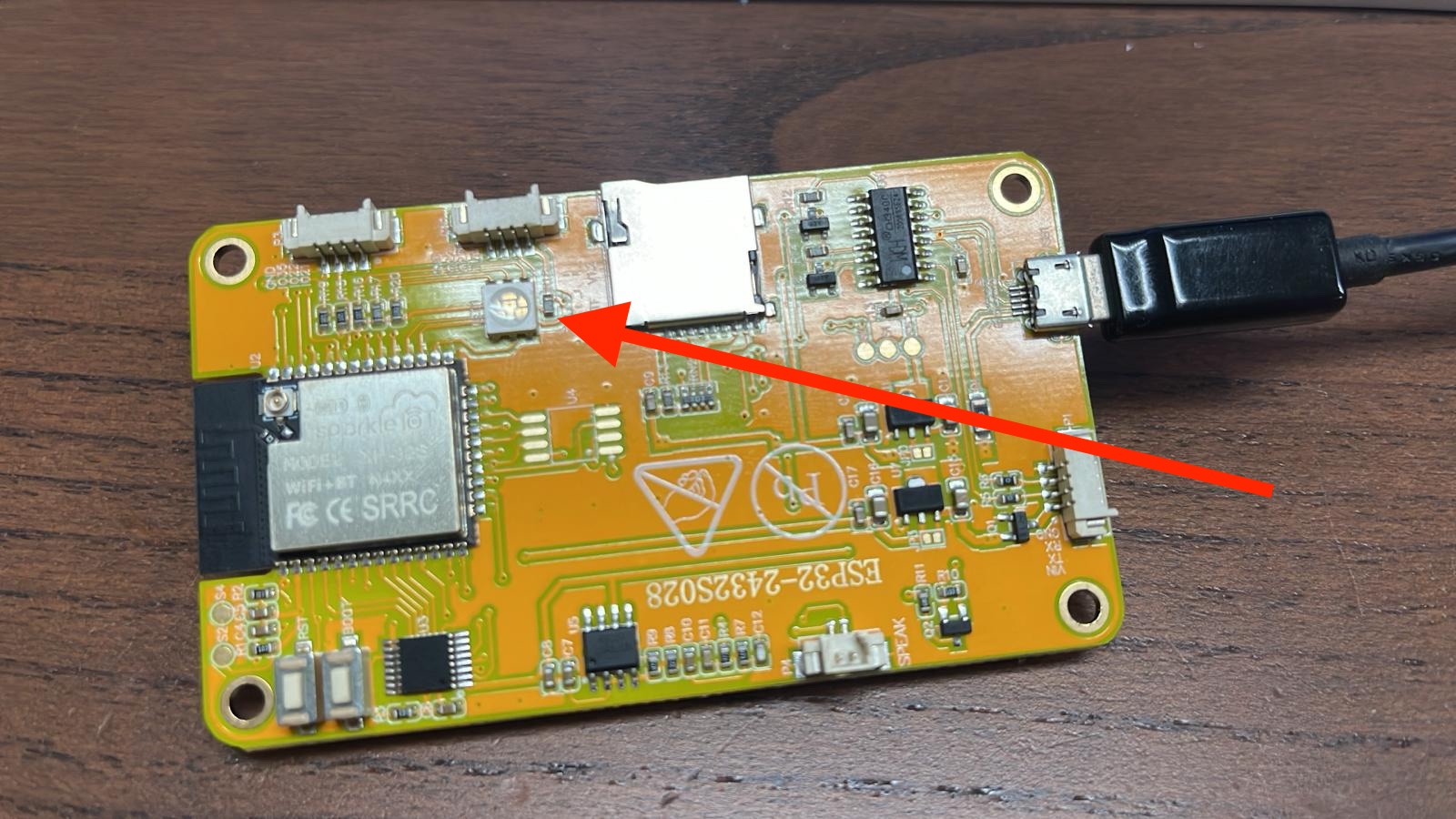
RGB LED
If your project requires additional pins to what is available elsewhere, this might be a good candidate to sacrifice.
Note: LEDs are "active low", meaning HIGH == off, LOW == on
| Pin | Use | Note |
|---|---|---|
| IO4 | Red LED | |
| IO16 | Green LED | |
| IO17 | Blue LED |
SD Card
Uses the VSPI Pin names are predefined in SPI.h
| Pin | Use | Note |
|---|---|---|
| IO5 | SS | |
| IO18 | SCK | |
| IO19 | MISO | |
| IO23 | MOSI |
Touch Screen
| Pin | Use | Note |
|---|---|---|
| IO25 | XPT2046_CLK | |
| IO32 | XPT2046_MOSI | |
| IO33 | XPT2046_CS | |
| IO36 | XPT2046_IRQ | |
| IO39 | XPT2046_MISO |
LDR (Light Sensor)
| Pin | Use | Note |
|---|---|---|
| IO34 |
Display
Uses the HSPI
| Pin | Use | Note |
|---|---|---|
| IO2 | TFT_RS | AKA: TFT_DC |
| IO12 | TFT_SDO | AKA: TFT_MISO |
| IO13 | TFT_SDI | AKA: TFT_MOSI |
| IO14 | TFT_SCK | |
| IO15 | TFT_CS | |
| IO21 | TFT_BL | Also on P3 connector, for some reason |
Test points
| Pad | Use | Note |
|---|---|---|
| S1 | GND | near USB-SERIAL |
| S2 | 3.3v | for ESP32 |
| S3 | 5v | near USB-SERIAL |
| S4 | GND | for ESP32 |
| S5 | 3.3v | for TFT |
| JP0 (pad nearest USB socket) | 5v | TFT LDO |
| JP0 | 3.3v | TFT LDO |
| JP3 (pad nearest USB socket) | 5v | ESP32 LDO |
| JP3 | 3.3v | ESP32 LDO |
More examples on https://github.com/quantrpeter/cheap-yellow-display-micropython-lvgl-example
Step 1: create Dockerfile
FROM ubuntu:22.04

# Install xclock and necessary X11 libraries
RUN apt-get update && apt-get install -y \
    x11-apps \
    && rm -rf /var/lib/apt/lists/*

# Set the DISPLAY environment variable
ENV DISPLAY=host.docker.internal:0

# Run xclock
CMD ["xclock"]
Step 2: Build the image
docker build -t xclock-ubuntu .
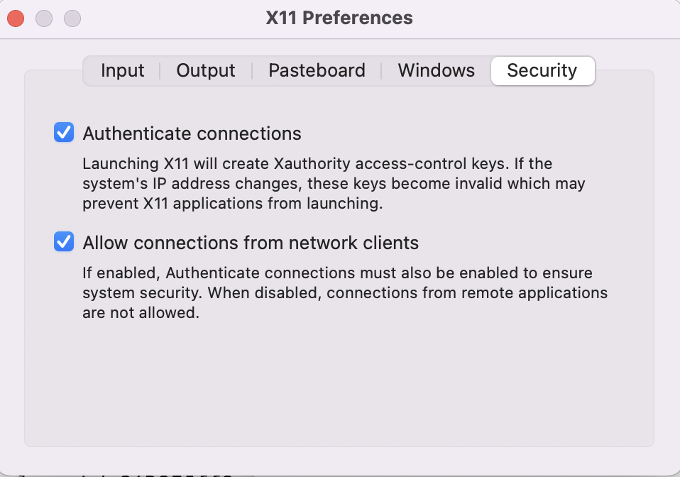
Step 3: Set XQuartz and restart it
Step 4: Run "xhost + 127.0.0.1", and this "xhost +localhost" wont work
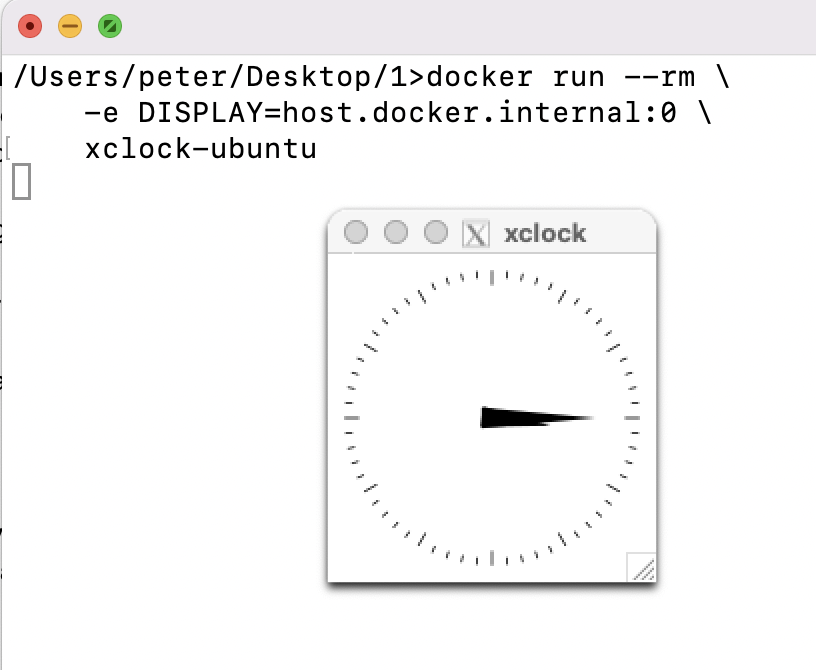
Step 5: Run
docker run --rm \
    -e DISPLAY=host.docker.internal:0 \
    xclock-ubuntu
Another way
docker run --name test -it ubuntu
apt-get update
apt-get install x11-apps
export DISPLAY=host.docker.internal:0
xclock
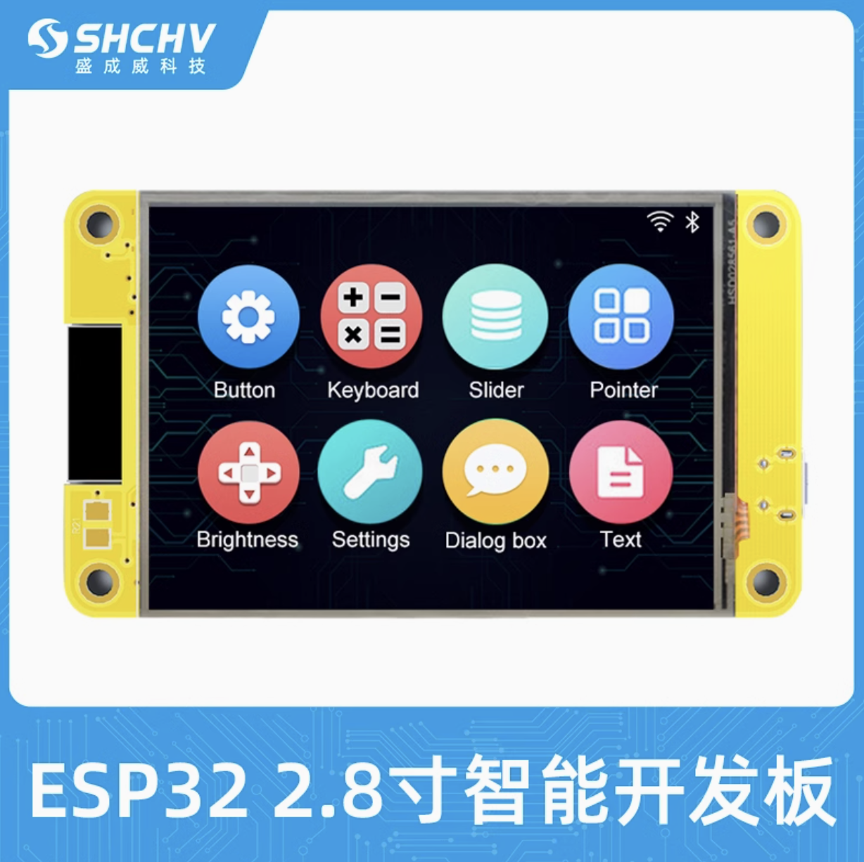
Official Tutorial From TaoBao Factory : https://github.com/quantrpeter/2.8inch_ESP32-2432S028R
Remark: use offset 0x1000 to write the firmware and have to erase flash first, so:
Download micropython firmware here https://micropython.org/download/ESP32_GENERIC/

1. esptool.py erase_flash
2. esptool.py --baud 460800 write_flash 0x1000 ESP32_GENERIC-20250415-v1.25.0.bin
Download All Files in below links, or by the attachment in this posts
ILI9341 Display Driver
Download ili9341.py from: github.com/rdagger/micropython-ili9341
XPT2046 Touchscreen Driver
Download xpt2046.py from: github.com/rdagger/micropython-ili9341
Font Library
For custom fonts, download xglcd_font.py and font files (e.g., Unispace12x24.c) from: github.com/rdagger/micropython-ili9341
CYD-Specific Library
For simplified control, use the cydr.py library from: github.com/jtobinart/MicroPython_CYD_ESP32-2432S028R
https://github.com/rdagger/micropython-ili9341/blob/master/fonts/Unispace12x24.c
Run it
mpremote cp cydr.py :cydr.py
mpremote cp ili9341.py :ili9341.py
mpremote cp xglcd_font.py :xglcd_font.py
mpremote cp xpt2046.py :xpt2046.py
mpremote mkdir fonts
mpremote cp Unispace12x24.c :fonts/Unispace12x24.c
mpremote cp main.py :main.py
mpremote exec "import main"

Below example only work with official micropython firmware. lv-micropython firmware won't work.
Example 1 : Animation.py
from machine import Pin, SPI
from ili9341 import Display, color565
import time

# Initialize SPI for ILI9341 display
display_spi = SPI(1, baudrate=60000000, sck=Pin(14), mosi=Pin(13))
display = Display(display_spi, dc=Pin(2), cs=Pin(15), rst=Pin(15), width=320, height=240, rotation=90)

# Turn on backlight
backlight = Pin(21, Pin.OUT)
backlight.on()

# Clear display (white background)
display.clear(color565(255, 255, 255))

# Animation parameters
rect_width = 30
rect_height = 30
x = 0
y = 0
dx = 6  # Increased speed
dy = 6  # Increased speed
rect_color = color565(255, 0, 0)  # Red rectangle
bg_color = color565(255, 255, 255)  # White background

# Animation loop
while True:
    # Clear previous rectangle (minimize cleared area)
    display.fill_rectangle(x, y, rect_width, rect_height, bg_color)

    # Update position
    x += dx
    y += dy

    # Bounce off edges
    if x <= 0 or x >= 320 - rect_width:
        dx = -dx
    if y <= 0 or y >= 240 - rect_height:
        dy = -dy

    # Draw new rectangle
    display.fill_rectangle(x, y, rect_width, rect_height, rect_color)

    # Reduced delay for faster animation
    time.sleep(0.02)  # ~50 FPS
Example 2 : Animation_complex.py
from machine import Pin, SPI
from ili9341 import Display, color565
from xglcd_font import XglcdFont
import time
import math

# Initialize SPI and ILI9341 display
display_spi = SPI(1, baudrate=60000000, sck=Pin(14), mosi=Pin(13))
display = Display(display_spi, dc=Pin(2), cs=Pin(15), rst=Pin(15), width=320, height=240, rotation=90)

# Turn on backlight
backlight = Pin(21, Pin.OUT)
backlight.on()

# Clear display (black background for contrast)
display.clear(color565(0, 0, 0))

# Load font
unispace = XglcdFont('fonts/Unispace12x24.c', 12, 24)

# Shape parameters (2 rectangles)
shapes = [
    {'type': 'rect', 'x': 50, 'y': 50, 'w': 25, 'h': 25, 'dx': 5, 'dy': 3},  # Rectangle 1
    {'type': 'rect', 'x': 100, 'y': 80, 'w': 20, 'h': 20, 'dx': -4, 'dy': 4}   # Rectangle 2
]

# Text parameters
text = "CYD Demo!"
text_x = 0
text_dx = 3
text_color = color565(255, 255, 255)  # White text
bg_color = color565(0, 0, 0)  # Black background

# Color transition parameters
color_phase = 0
color_cycle_speed = 0.1  # Faster color change

# Animation loop
while True:
    # Clear previous text
    display.fill_rectangle(text_x, 0, unispace.measure_text(text), 24, bg_color)

    # Update text position
    text_x += text_dx
    if text_x <= 0 or text_x >= 320 - unispace.measure_text(text):
        text_dx = -text_dx

    # Draw text
    display.draw_text(text_x, 0, text, unispace, text_color)

    # Update color phase (simplified)
    color_phase = (color_phase + color_cycle_speed) % (2 * math.pi)
    r = int(127 * (1 + math.sin(color_phase)))
    g = int(127 * (1 + math.cos(color_phase)))
    b = 128  # Fixed blue for simplicity
    shape_color = color565(r, g, b)

    # Update and draw shapes
    for shape in shapes:
        # Clear previous shape
        display.fill_rectangle(shape['x'], shape['y'], shape['w'], shape['h'], bg_color)

        # Update position
        shape['x'] += shape['dx']
        shape['y'] += shape['dy']

        # Bounce off edges (avoid text area)
        if shape['x'] <= 0 or shape['x'] >= 320 - shape['w']:
            shape['dx'] = -shape['dx']
        if shape['y'] <= 24 or shape['y'] >= 240 - shape['h']:
            shape['dy'] = -shape['dy']

        # Draw new shape
        display.fill_rectangle(shape['x'], shape['y'], shape['w'], shape['h'], shape_color)

    # Delay for ~66 FPS
    time.sleep(0.015)
In mac, sometime arduino unable to write the program to cheap yellow display esp32, you can type the command manually
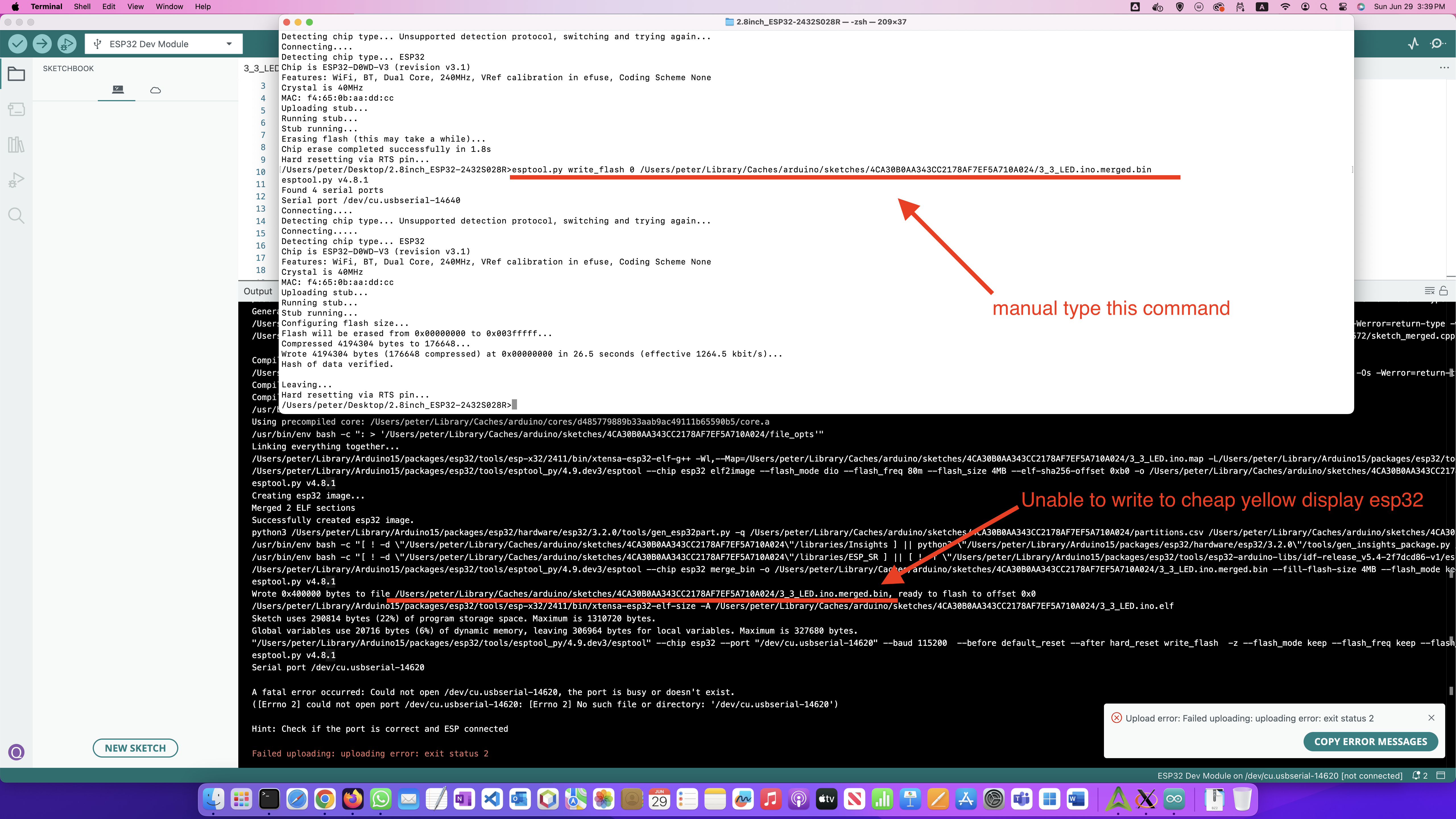


If you have this problem:

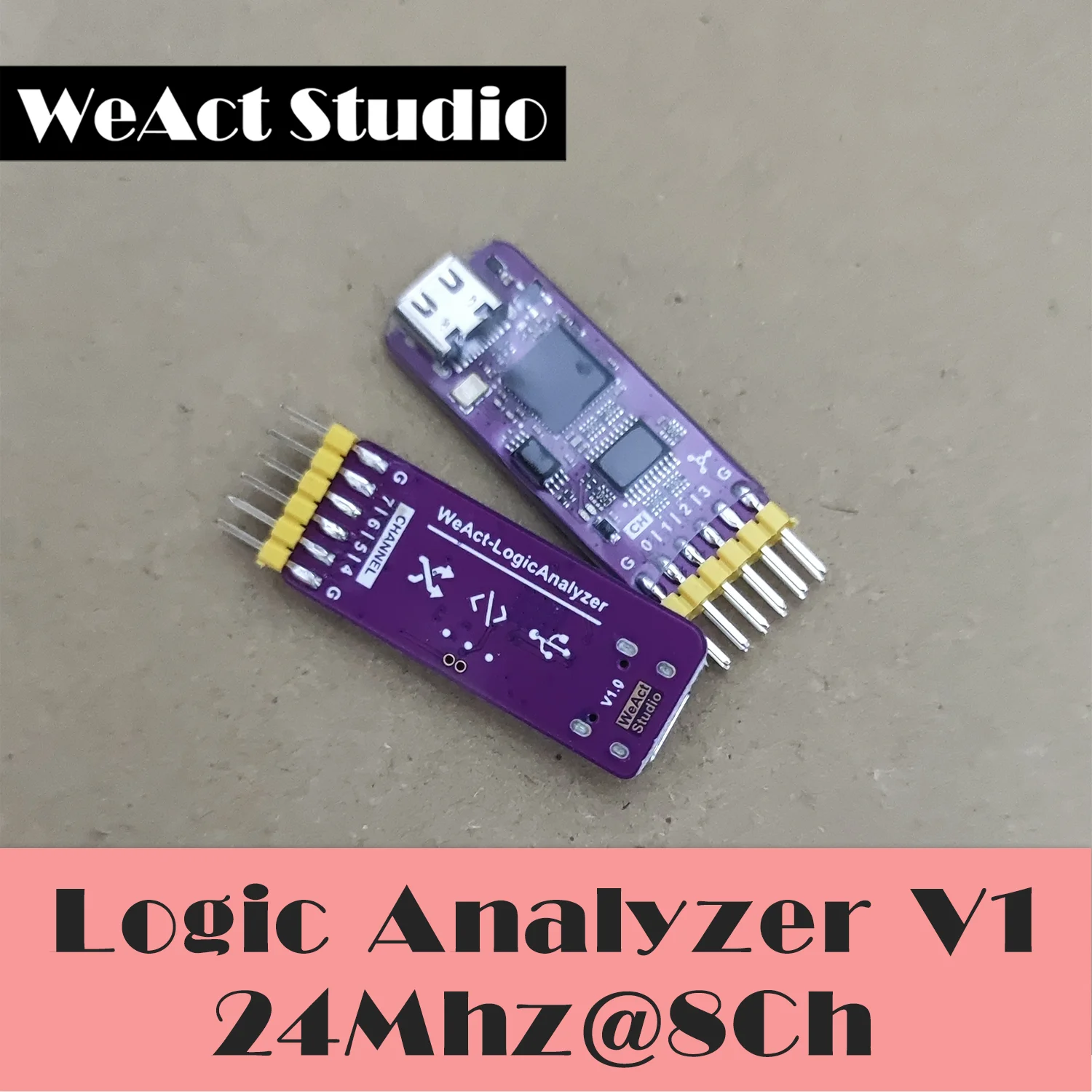
run: sigrok-cli --loglevel 5 -d fx2lafw --scan , it said failed to find the firmware file

So build this project and restart terminal, then you will success
git clone git://sigrok.org/sigrok-firmware-fx2lafw
cd sigrok-firmware-fx2lafw
./autogen.sh
./configure
make
sudo make install

sigrok-cli --driver fx2lafw:conn=20.59 -g Logic --samples 80 -O ascii:width=80:charset='_"\/'
It has no SoftI2C, so change
display = ssd1306.SSD1306_I2C(128, 64, SoftI2C(sda=Pin(20), scl=Pin(21)))
to
import time
from machine import Pin, I2C, SoftI2C
import ssd1306
i2c = I2C(1) # Create I2C object
display = ssd1306.SSD1306_I2C(128, 64, i2c) # Pass I2C object
display.fill(0)
display.text("Hello, World", 0, 0)
display.show()
time.sleep(100)
- git clone https://github.com/micropython/micropython.git
- cd micropython
- docker run -it -v .:/micropython --name micropython ubuntu
- apt-get update
- apt-get install -y gcc g++ make automake python3 git gcc-arm-none-eabi
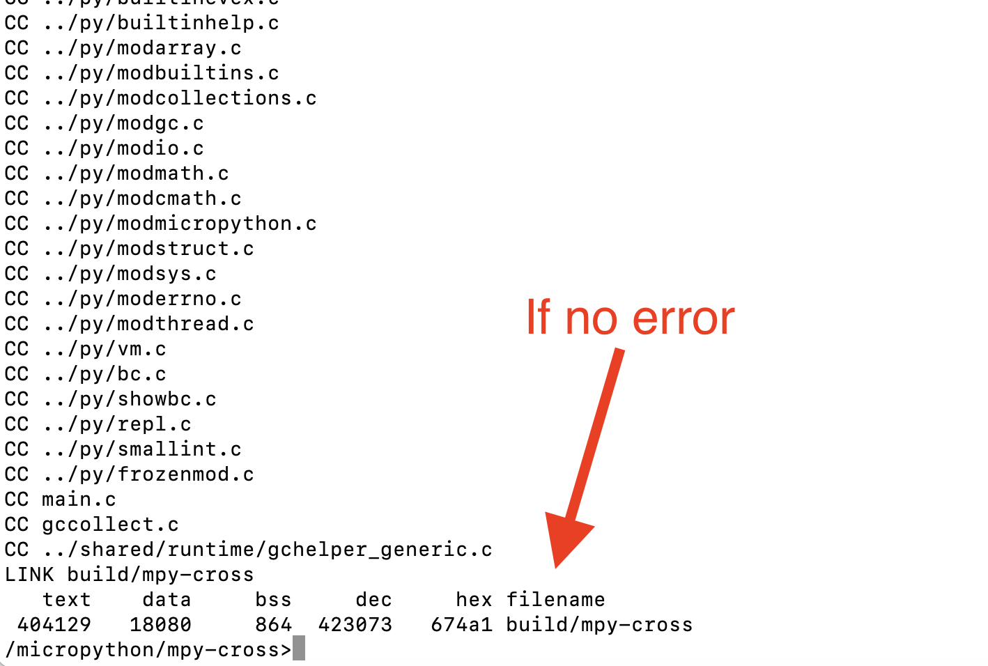
- cd /micropython/mpy-cross
- make
- cd ../ports/stm32
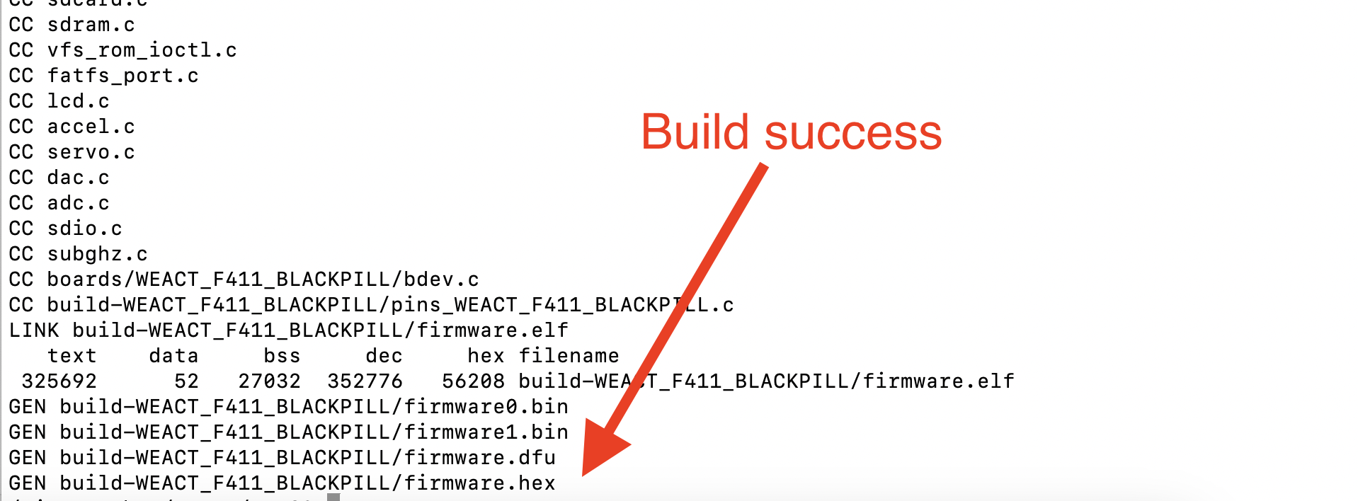
- make BOARD=WEACT_F411_BLACKPILL submodules
- make BOARD=WEACT_F411_BLACKPILL
- exit docker
- in mac: brew install dfu-uril
- cd to micropython/ports/stm32
- st-info --probe
- st-flash erase
- st-flash --format ihex write build-WEACT_F411_BLACKPILL/firmware.hex
using st-flash is better then dfu-util because we don't need to put the board into dfu mode

- pip install mpremote
- mpremote
- mremote fs ls
- ctrl+] to exit

IT IS SSH1106,NOT SSD1306
#
# MicroPython SH1106 OLED driver, I2C and SPI interfaces
#
# The MIT License (MIT)
#
# Copyright (c) 2016 Radomir Dopieralski (@deshipu),
# 2017-2021 Robert Hammelrath (@robert-hh)
# 2021 Tim Weber (@scy)
#
# Permission is hereby granted, free of charge, to any person obtaining a copy
# of this software and associated documentation files (the "Software"), to deal
# in the Software without restriction, including without limitation the rights
# to use, copy, modify, merge, publish, distribute, sublicense, and/or sell
# copies of the Software, and to permit persons to whom the Software is
# furnished to do so, subject to the following conditions:
#
# The above copyright notice and this permission notice shall be included in
# all copies or substantial portions of the Software.
#
# THE SOFTWARE IS PROVIDED "AS IS", WITHOUT WARRANTY OF ANY KIND, EXPRESS OR
# IMPLIED, INCLUDING BUT NOT LIMITED TO THE WARRANTIES OF MERCHANTABILITY,
# FITNESS FOR A PARTICULAR PURPOSE AND NONINFRINGEMENT. IN NO EVENT SHALL THE
# AUTHORS OR COPYRIGHT HOLDERS BE LIABLE FOR ANY CLAIM, DAMAGES OR OTHER
# LIABILITY, WHETHER IN AN ACTION OF CONTRACT, TORT OR OTHERWISE, ARISING FROM,
# OUT OF OR IN CONNECTION WITH THE SOFTWARE OR THE USE OR OTHER DEALINGS IN
# THE SOFTWARE.
#
# Sample code sections for ESP8266 pin assignments
# ------------ SPI ------------------
# Pin Map SPI
# - 3v - xxxxxx - Vcc
# - G - xxxxxx - Gnd
# - D7 - GPIO 13 - Din / MOSI fixed
# - D5 - GPIO 14 - Clk / Sck fixed
# - D8 - GPIO 4 - CS (optional, if the only connected device)
# - D2 - GPIO 5 - D/C
# - D1 - GPIO 2 - Res
#
# for CS, D/C and Res other ports may be chosen.
#
# from machine import Pin, SPI
# import sh1106
# spi = SPI(1, baudrate=1000000)
# display = sh1106.SH1106_SPI(128, 64, spi, Pin(5), Pin(2), Pin(4))
# display.sleep(False)
# display.fill(0)
# display.text('Testing 1', 0, 0, 1)
# display.show()
#
# --------------- I2C ------------------
#
# Pin Map I2C
# - 3v - xxxxxx - Vcc
# - G - xxxxxx - Gnd
# - D2 - GPIO 5 - SCK / SCL
# - D1 - GPIO 4 - DIN / SDA
# - D0 - GPIO 16 - Res
# - G - xxxxxx CS
# - G - xxxxxx D/C
#
# Pin's for I2C can be set almost arbitrary
#
# from machine import Pin, I2C
# import sh1106
#
# i2c = I2C(scl=Pin(5), sda=Pin(4), freq=400000)
# display = sh1106.SH1106_I2C(128, 64, i2c, Pin(16), 0x3c)
# display.sleep(False)
# display.fill(0)
# display.text('Testing 1', 0, 0, 1)
# display.show()
from micropython import const
import utime as time
import framebuf
# a few register definitions
_SET_CONTRAST = const(0x81)
_SET_NORM_INV = const(0xa6)
_SET_DISP = const(0xae)
_SET_SCAN_DIR = const(0xc0)
_SET_SEG_REMAP = const(0xa0)
_LOW_COLUMN_ADDRESS = const(0x00)
_HIGH_COLUMN_ADDRESS = const(0x10)
_SET_PAGE_ADDRESS = const(0xB0)
class SH1106(framebuf.FrameBuffer):
def __init__(self, width, height, external_vcc, rotate=0):
self.width = width
self.height = height
self.external_vcc = external_vcc
self.flip_en = rotate == 180 or rotate == 270
self.rotate90 = rotate == 90 or rotate == 270
self.pages = self.height // 8
self.bufsize = self.pages * self.width
self.renderbuf = bytearray(self.bufsize)
self.pages_to_update = 0
self.delay = 0
if self.rotate90:
self.displaybuf = bytearray(self.bufsize)
# HMSB is required to keep the bit order in the render buffer
# compatible with byte-for-byte remapping to the display buffer,
# which is in VLSB. Else we'd have to copy bit-by-bit!
super().__init__(self.renderbuf, self.height, self.width,
framebuf.MONO_HMSB)
else:
self.displaybuf = self.renderbuf
super().__init__(self.renderbuf, self.width, self.height,
framebuf.MONO_VLSB)
# flip() was called rotate() once, provide backwards compatibility.
self.rotate = self.flip
self.init_display()
# abstractmethod
def write_cmd(self, *args, **kwargs):
raise NotImplementedError
# abstractmethod
def write_data(self, *args, **kwargs):
raise NotImplementedError
def init_display(self):
self.reset()
self.fill(0)
self.show()
self.poweron()
# rotate90 requires a call to flip() for setting up.
self.flip(self.flip_en)
def poweroff(self):
self.write_cmd(_SET_DISP | 0x00)
def poweron(self):
self.write_cmd(_SET_DISP | 0x01)
if self.delay:
time.sleep_ms(self.delay)
def flip(self, flag=None, update=True):
if flag is None:
flag = not self.flip_en
mir_v = flag ^ self.rotate90
mir_h = flag
self.write_cmd(_SET_SEG_REMAP | (0x01 if mir_v else 0x00))
self.write_cmd(_SET_SCAN_DIR | (0x08 if mir_h else 0x00))
self.flip_en = flag
if update:
self.show(True) # full update
def sleep(self, value):
self.write_cmd(_SET_DISP | (not value))
def contrast(self, contrast):
self.write_cmd(_SET_CONTRAST)
self.write_cmd(contrast)
def invert(self, invert):
self.write_cmd(_SET_NORM_INV | (invert & 1))
def show(self, full_update = False):
# self.* lookups in loops take significant time (~4fps).
(w, p, db, rb) = (self.width, self.pages,
self.displaybuf, self.renderbuf)
if self.rotate90:
for i in range(self.bufsize):
db[w * (i % p) + (i // p)] = rb[i]
if full_update:
pages_to_update = (1 << self.pages) - 1
else:
pages_to_update = self.pages_to_update
#print("Updating pages: {:08b}".format(pages_to_update))
for page in range(self.pages):
if (pages_to_update & (1 << page)):
self.write_cmd(_SET_PAGE_ADDRESS | page)
self.write_cmd(_LOW_COLUMN_ADDRESS | 2)
self.write_cmd(_HIGH_COLUMN_ADDRESS | 0)
self.write_data(db[(w*page):(w*page+w)])
self.pages_to_update = 0
def pixel(self, x, y, color=None):
if color is None:
return super().pixel(x, y)
else:
super().pixel(x, y , color)
page = y // 8
self.pages_to_update |= 1 << page
def text(self, text, x, y, color=1):
super().text(text, x, y, color)
self.register_updates(y, y+7)
def line(self, x0, y0, x1, y1, color):
super().line(x0, y0, x1, y1, color)
self.register_updates(y0, y1)
def hline(self, x, y, w, color):
super().hline(x, y, w, color)
self.register_updates(y)
def vline(self, x, y, h, color):
super().vline(x, y, h, color)
self.register_updates(y, y+h-1)
def fill(self, color):
super().fill(color)
self.pages_to_update = (1 << self.pages) - 1
def blit(self, fbuf, x, y, key=-1, palette=None):
super().blit(fbuf, x, y, key, palette)
self.register_updates(y, y+self.height)
def scroll(self, x, y):
# my understanding is that scroll() does a full screen change
super().scroll(x, y)
self.pages_to_update = (1 << self.pages) - 1
def fill_rect(self, x, y, w, h, color):
super().fill_rect(x, y, w, h, color)
self.register_updates(y, y+h-1)
def rect(self, x, y, w, h, color):
super().rect(x, y, w, h, color)
self.register_updates(y, y+h-1)
def ellipse(self, x, y, xr, yr, color):
super().ellipse(x, y, xr, yr, color)
self.register_updates(y-yr, y+yr-1)
def register_updates(self, y0, y1=None):
# this function takes the top and optional bottom address of the changes made
# and updates the pages_to_change list with any changed pages
# that are not yet on the list
start_page = max(0, y0 // 8)
end_page = max(0, y1 // 8) if y1 is not None else start_page
# rearrange start_page and end_page if coordinates were given from bottom to top
if start_page > end_page:
start_page, end_page = end_page, start_page
for page in range(start_page, end_page+1):
self.pages_to_update |= 1 << page
def reset(self, res=None):
if res is not None:
res(1)
time.sleep_ms(1)
res(0)
time.sleep_ms(20)
res(1)
time.sleep_ms(20)
class SH1106_I2C(SH1106):
def __init__(self, width, height, i2c, res=None, addr=0x3c,
rotate=0, external_vcc=False, delay=0):
self.i2c = i2c
self.addr = addr
self.res = res
self.temp = bytearray(2)
self.delay = delay
if res is not None:
res.init(res.OUT, value=1)
super().__init__(width, height, external_vcc, rotate)
def write_cmd(self, cmd):
self.temp[0] = 0x80 # Co=1, D/C#=0
self.temp[1] = cmd
self.i2c.writeto(self.addr, self.temp)
def write_data(self, buf):
self.i2c.writeto(self.addr, b'\x40'+buf)
def reset(self,res=None):
super().reset(self.res)
class SH1106_SPI(SH1106):
def __init__(self, width, height, spi, dc, res=None, cs=None,
rotate=0, external_vcc=False, delay=0):
dc.init(dc.OUT, value=0)
if res is not None:
res.init(res.OUT, value=0)
if cs is not None:
cs.init(cs.OUT, value=1)
self.spi = spi
self.dc = dc
self.res = res
self.cs = cs
self.delay = delay
super().__init__(width, height, external_vcc, rotate)
def write_cmd(self, cmd):
if self.cs is not None:
self.cs(1)
self.dc(0)
self.cs(0)
self.spi.write(bytearray([cmd]))
self.cs(1)
else:
self.dc(0)
self.spi.write(bytearray([cmd]))
def write_data(self, buf):
if self.cs is not None:
self.cs(1)
self.dc(1)
self.cs(0)
self.spi.write(buf)
self.cs(1)
else:
self.dc(1)
self.spi.write(buf)
def reset(self, res=None):
super().reset(self.res)
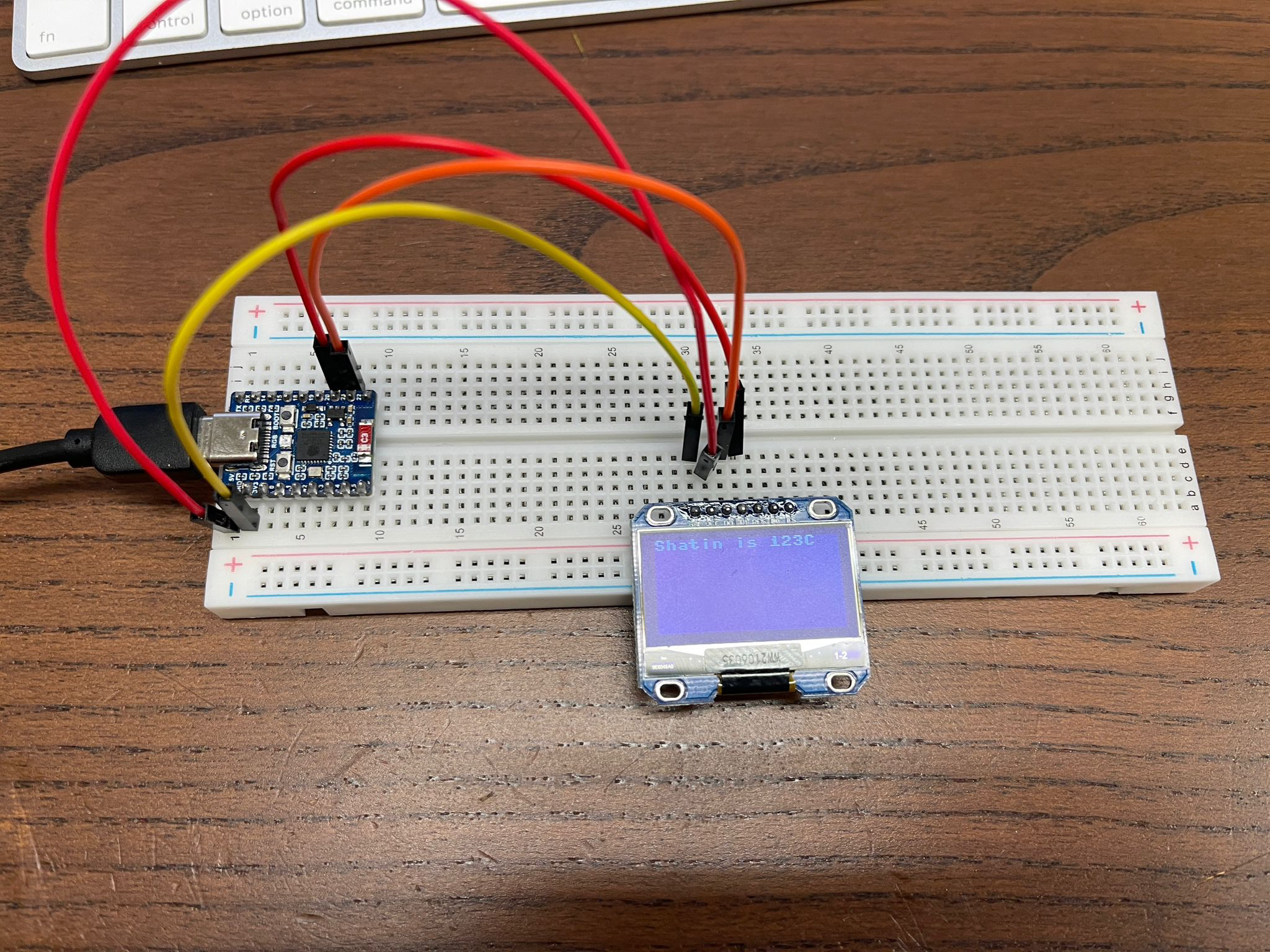
from machine import Pin, I2C
i2c = I2C(scl=Pin(21), sda=Pin(20), freq=400000)
display = SH1106_I2C(128, 64, i2c, Pin(16), 0x3c)
display.sleep(False)
display.fill(0)
display.rotate(180)
display.text("Shatin is "+str(123)+"C", 0, 0)
display.show()
#include <Arduino.h>

int freq = 2000;    // frequency
int channel = 0;    // aisle
int resolution = 8;   // Resolution

const int led = 4;
void setup()
{
  //Initialize GPIO, turn off tricolor light

  pinMode(4, OUTPUT);
  pinMode(17, OUTPUT);
  pinMode(16, OUTPUT);
  digitalWrite(4, 0);
  digitalWrite(16, 0);
  digitalWrite(17, 0);
  ledcAttach(channel, freq, resolution); // set channel
  //ledcAttachPin(led, channel);  // Connect the channel to the corresponding pin
}

void loop()
{
  digitalWrite(4, 0);
  digitalWrite(16, 1);
  digitalWrite(17, 1);
  delay(500);
  digitalWrite(4, 1);
  digitalWrite(16, 0);
  digitalWrite(17, 1);
  delay(500);
  digitalWrite(4, 1);
  digitalWrite(16, 1);
  digitalWrite(17, 0);
  delay(500);
  digitalWrite(4, 1);
  digitalWrite(16, 1);
  digitalWrite(17, 1);
  delay(500);
}

(Set to 115200, otherwise upload will fail)
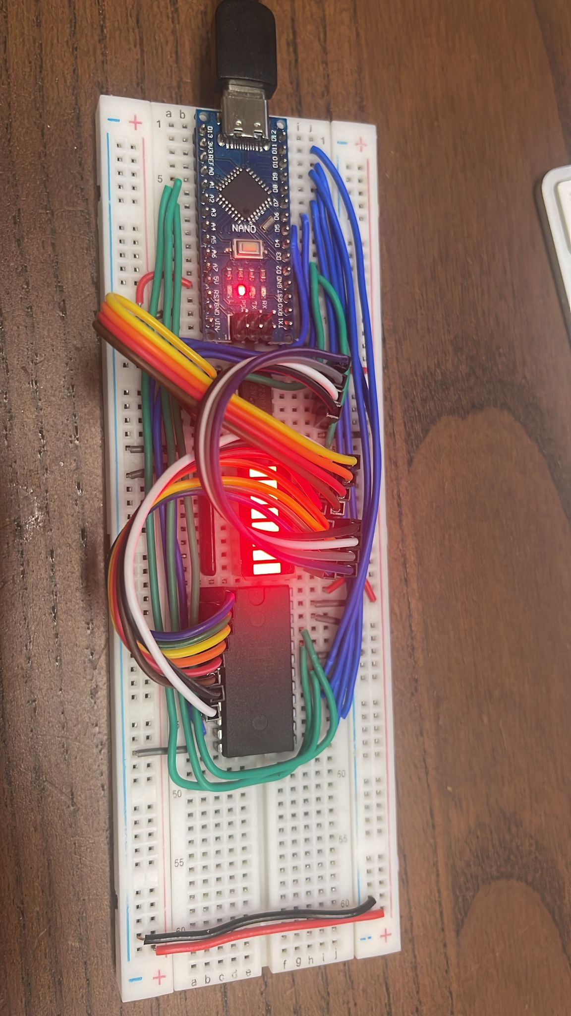
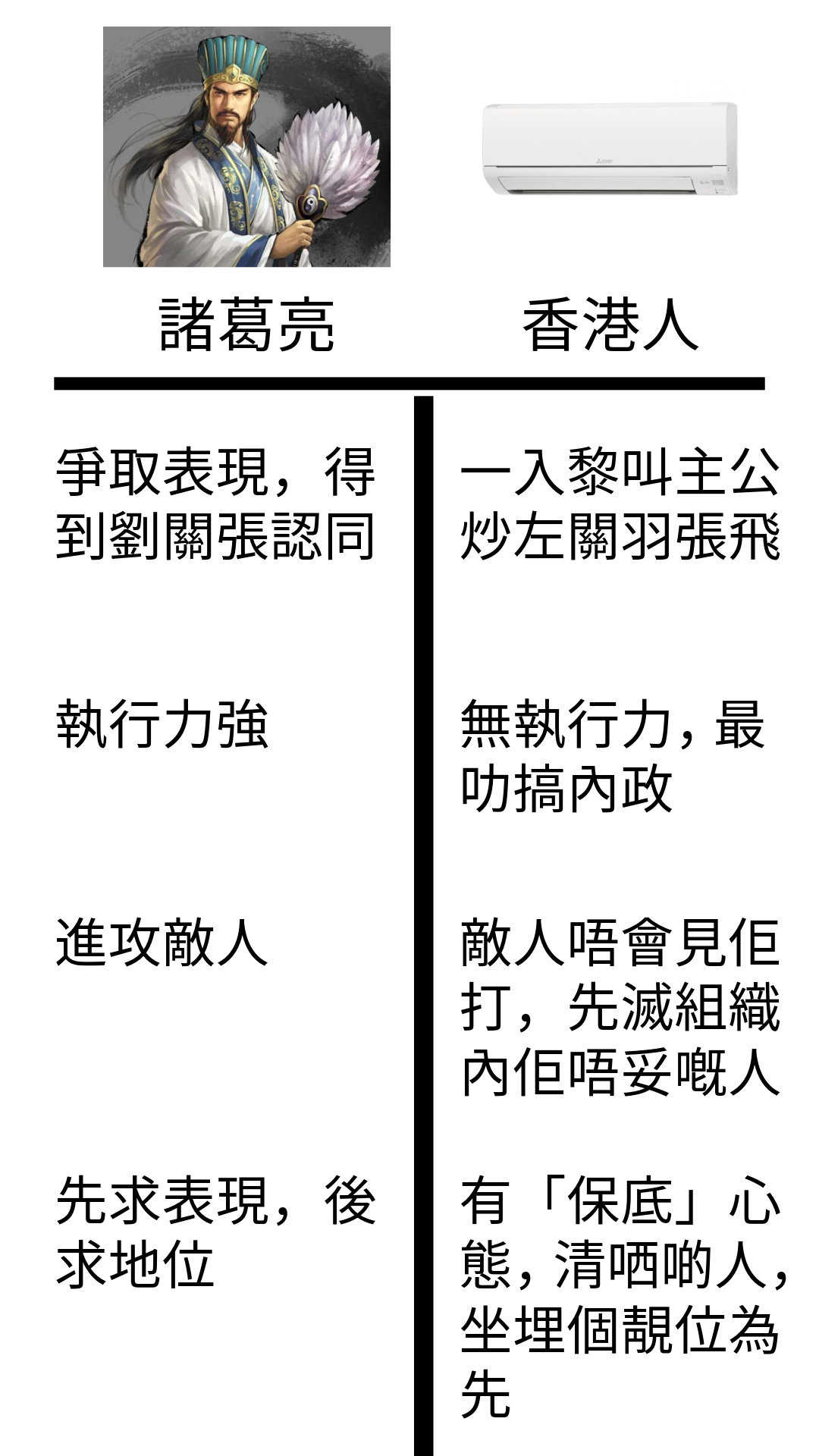
諸葛亮勁係無資源嘅情況底下可以有高強嘅執行力。而香港人絕大部份都無執行力。

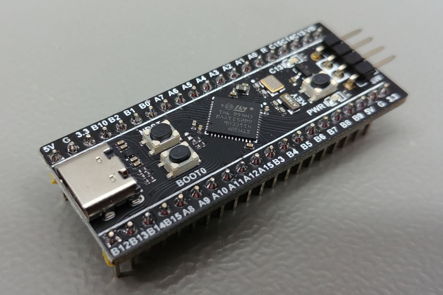
https://gitlab.quantr.hk/example/stm32/stm32f411ceu6-74hc595-shift-register
/* USER CODE BEGIN Header */
/**
 ******************************************************************************
 * @file           : main.c
 * @brief          : Main program body
 ******************************************************************************
 * @attention
 *
 * Copyright (c) 2025 STMicroelectronics.
 * All rights reserved.
 *
 * This software is licensed under terms that can be found in the LICENSE file
 * in the root directory of this software component.
 * If no LICENSE file comes with this software, it is provided AS-IS.
 *
 ******************************************************************************
 */
/* USER CODE END Header */
/* Includes ------------------------------------------------------------------*/
#include "main.h"

/* Private includes ----------------------------------------------------------*/
/* USER CODE BEGIN Includes */

/* USER CODE END Includes */

/* Private typedef -----------------------------------------------------------*/
/* USER CODE BEGIN PTD */

/* USER CODE END PTD */

/* Private define ------------------------------------------------------------*/
/* USER CODE BEGIN PD */

/* USER CODE END PD */

/* Private macro -------------------------------------------------------------*/
/* USER CODE BEGIN PM */

/* USER CODE END PM */

/* Private variables ---------------------------------------------------------*/

/* USER CODE BEGIN PV */
void HC595_Send_Data(unsigned short data) {
	char i = 0;
	for (i = 0; i < 16; i++) {
		if (data & 0x1) {
			HAL_GPIO_WritePin(data_in_GPIO_Port, data_in_Pin, 1);
		} else {
			HAL_GPIO_WritePin(data_in_GPIO_Port, data_in_Pin, 0);
		}

		HAL_GPIO_WritePin(clock_in_GPIO_Port, clock_in_Pin, 0);
		HAL_Delay(5);
		HAL_GPIO_WritePin(clock_in_GPIO_Port, clock_in_Pin, 1);
		HAL_Delay(5);
		data >>= 1;
	}

	HAL_GPIO_WritePin(register_clock_in_GPIO_Port, register_clock_in_Pin, 0);
	HAL_Delay(5);
	HAL_GPIO_WritePin(register_clock_in_GPIO_Port, register_clock_in_Pin, 1);
	HAL_Delay(5);
}
/* USER CODE END PV */

/* Private function prototypes -----------------------------------------------*/
void SystemClock_Config(void);
static void MX_GPIO_Init(void);
/* USER CODE BEGIN PFP */

/* USER CODE END PFP */

/* Private user code ---------------------------------------------------------*/
/* USER CODE BEGIN 0 */

/* USER CODE END 0 */

/**
  * @brief  The application entry point.
  * @retval int
  */
int main(void)
{

  /* USER CODE BEGIN 1 */

  /* USER CODE END 1 */

  /* MCU Configuration--------------------------------------------------------*/

  /* Reset of all peripherals, Initializes the Flash interface and the Systick. */
  HAL_Init();

  /* USER CODE BEGIN Init */

  /* USER CODE END Init */

  /* Configure the system clock */
  SystemClock_Config();

  /* USER CODE BEGIN SysInit */

  /* USER CODE END SysInit */

  /* Initialize all configured peripherals */
  MX_GPIO_Init();
  /* USER CODE BEGIN 2 */

  /* USER CODE END 2 */

  /* Infinite loop */
  /* USER CODE BEGIN WHILE */
	unsigned short x = 0;
	while (1) {
    /* USER CODE END WHILE */

    /* USER CODE BEGIN 3 */
		HC595_Send_Data(x);

		x++;
		HAL_Delay(50);
	}
  /* USER CODE END 3 */
}

/**
  * @brief System Clock Configuration
  * @retval None
  */
void SystemClock_Config(void)
{
  RCC_OscInitTypeDef RCC_OscInitStruct = {0};
  RCC_ClkInitTypeDef RCC_ClkInitStruct = {0};

  /** Configure the main internal regulator output voltage
  */
  __HAL_RCC_PWR_CLK_ENABLE();
  __HAL_PWR_VOLTAGESCALING_CONFIG(PWR_REGULATOR_VOLTAGE_SCALE1);

  /** Initializes the RCC Oscillators according to the specified parameters
  * in the RCC_OscInitTypeDef structure.
  */
  RCC_OscInitStruct.OscillatorType = RCC_OSCILLATORTYPE_HSI;
  RCC_OscInitStruct.HSIState = RCC_HSI_ON;
  RCC_OscInitStruct.HSICalibrationValue = RCC_HSICALIBRATION_DEFAULT;
  RCC_OscInitStruct.PLL.PLLState = RCC_PLL_NONE;
  if (HAL_RCC_OscConfig(&RCC_OscInitStruct) != HAL_OK)
  {
    Error_Handler();
  }

  /** Initializes the CPU, AHB and APB buses clocks
  */
  RCC_ClkInitStruct.ClockType = RCC_CLOCKTYPE_HCLK|RCC_CLOCKTYPE_SYSCLK
                              |RCC_CLOCKTYPE_PCLK1|RCC_CLOCKTYPE_PCLK2;
  RCC_ClkInitStruct.SYSCLKSource = RCC_SYSCLKSOURCE_HSI;
  RCC_ClkInitStruct.AHBCLKDivider = RCC_SYSCLK_DIV1;
  RCC_ClkInitStruct.APB1CLKDivider = RCC_HCLK_DIV1;
  RCC_ClkInitStruct.APB2CLKDivider = RCC_HCLK_DIV1;

  if (HAL_RCC_ClockConfig(&RCC_ClkInitStruct, FLASH_LATENCY_0) != HAL_OK)
  {
    Error_Handler();
  }
}

/**
  * @brief GPIO Initialization Function
  * @param None
  * @retval None
  */
static void MX_GPIO_Init(void)
{
  GPIO_InitTypeDef GPIO_InitStruct = {0};
  /* USER CODE BEGIN MX_GPIO_Init_1 */

  /* USER CODE END MX_GPIO_Init_1 */

  /* GPIO Ports Clock Enable */
  __HAL_RCC_GPIOA_CLK_ENABLE();
  __HAL_RCC_GPIOB_CLK_ENABLE();

  /*Configure GPIO pin Output Level */
  HAL_GPIO_WritePin(clock_in_GPIO_Port, clock_in_Pin, GPIO_PIN_RESET);

  /*Configure GPIO pin Output Level */
  HAL_GPIO_WritePin(GPIOB, register_clock_in_Pin|data_in_Pin, GPIO_PIN_RESET);

  /*Configure GPIO pin : clock_in_Pin */
  GPIO_InitStruct.Pin = clock_in_Pin;
  GPIO_InitStruct.Mode = GPIO_MODE_OUTPUT_PP;
  GPIO_InitStruct.Pull = GPIO_NOPULL;
  GPIO_InitStruct.Speed = GPIO_SPEED_FREQ_LOW;
  HAL_GPIO_Init(clock_in_GPIO_Port, &GPIO_InitStruct);

  /*Configure GPIO pins : register_clock_in_Pin data_in_Pin */
  GPIO_InitStruct.Pin = register_clock_in_Pin|data_in_Pin;
  GPIO_InitStruct.Mode = GPIO_MODE_OUTPUT_PP;
  GPIO_InitStruct.Pull = GPIO_NOPULL;
  GPIO_InitStruct.Speed = GPIO_SPEED_FREQ_LOW;
  HAL_GPIO_Init(GPIOB, &GPIO_InitStruct);

  /* USER CODE BEGIN MX_GPIO_Init_2 */

  /* USER CODE END MX_GPIO_Init_2 */
}

/* USER CODE BEGIN 4 */

/* USER CODE END 4 */

/**
  * @brief  This function is executed in case of error occurrence.
  * @retval None
  */
void Error_Handler(void)
{
  /* USER CODE BEGIN Error_Handler_Debug */
	/* User can add his own implementation to report the HAL error return state */
	__disable_irq();
	while (1) {
	}
  /* USER CODE END Error_Handler_Debug */
}

#ifdef  USE_FULL_ASSERT
/**
  * @brief  Reports the name of the source file and the source line number
  *         where the assert_param error has occurred.
  * @param  file: pointer to the source file name
  * @param  line: assert_param error line source number
  * @retval None
  */
void assert_failed(uint8_t *file, uint32_t line)
{
  /* USER CODE BEGIN 6 */
  /* User can add his own implementation to report the file name and line number,
     ex: printf("Wrong parameters value: file %s on line %d\r\n", file, line) */
  /* USER CODE END 6 */
}
#endif /* USE_FULL_ASSERT */

This is the tutorial to compile micropython with LVGL and burn it into the board
Steps:
git clone https://github.com/lvgl-micropython/lvgl_micropython.git
cd lvgl_micropython
python3 make.py esp32 clean \
  --flash-size=4 \
  --enable-jtag-repl=y \
  BOARD=ESP32_GENERIC_C6 \
  DISPLAY=st7789
esptool.py erase_flash
esptool.py --baud 460800 write_flash 0 build/lvgl_micropy_ESP32_GENERIC_C6-4.bin
If success, you should see this

Open thonny and run
import lcd_bus
from micropython import const
import machine


# display settings
_WIDTH = const(172)
_HEIGHT = const(320)
_BL = const(22)
_RST = const(21)
_DC = const(15)

_MOSI = const(6)
_MISO = const(5)
_SCK = const(7)
_HOST = const(1)  # SPI2

_LCD_CS = const(14)
_LCD_FREQ = const(80000000)

_OFFSET_X = const(34)
_OFFSET_Y = const(0)

print('s1');
spi_bus = machine.SPI.Bus(
    host=_HOST,
    mosi=_MOSI,
    miso=_MISO,
    sck=_SCK
)

print('s2');
display_bus = lcd_bus.SPIBus(
    spi_bus=spi_bus,
    freq=_LCD_FREQ,
    dc=_DC,
    cs=_LCD_CS,
)

# we are going to let the display driver sort out the best freame buffer size and where to allocate it to.
# fb1 = display_bus.allocate_framebuffer(_BUFFER_SIZE, lcd_bus.MEMORY_INTERNAL | lcd_bus.MEMORY_DMA)
# fb2 = display_bus.allocate_framebuffer(_BUFFER_SIZE, lcd_bus.MEMORY_INTERNAL | lcd_bus.MEMORY_DMA)

import st7789  # NOQA
import lvgl as lv  # NOQA

print('s3');
display = st7789.ST7789(
    data_bus=display_bus,
    display_width=_WIDTH,
    display_height=_HEIGHT,
    backlight_pin=_BL,
    reset_pin=_RST,
    reset_state=st7789.STATE_LOW,
    backlight_on_state=st7789.STATE_PWM,
    color_space=lv.COLOR_FORMAT.RGB565,
    color_byte_order=st7789.BYTE_ORDER_RGB,
    rgb565_byte_swap=True,
    offset_x=_OFFSET_X,
    offset_y=_OFFSET_Y,
)

print('s4');
import task_handler  # NOQA

display.set_power(True)
display.init()
display.set_backlight(100)

th = task_handler.TaskHandler()

scrn = lv.screen_active()
scrn.set_style_bg_color(lv.color_hex(0x000000), 0)

label = lv.label(scrn)
label.set_text('HELLO WORLD!')
label.align(lv.ALIGN.CENTER, 0, 0)

print('end');
Then you will see
Links you should read
https://www.waveshare.com/wiki/ESP32-C6-LCD-1.47
https://github.com/lvgl-micropython/lvgl_micropython
Remark:
This program is a little bit crazy, first time you run it will success, but if you run second time, it has error, see below. You need to press the rst button on board before rerun


from machine import Pin
import neopixel
import time

pixels = neopixel.NeoPixel(Pin(8, Pin.OUT), 1)

while True:
	pixels[0] = (0xff, 0x00, 0x00)
	pixels.write()
	time.sleep(1)
	pixels[0] = (0x00, 0xff, 0x00)
	pixels.write()
	time.sleep(1)
	pixels[0] = (0x00, 0x00, 0xff)
	pixels.write()
	time.sleep(1)
	pixels[0] = (0xff, 0xff, 0x00)
	pixels.write()
	time.sleep(1)
	pixels[0] = (0x00, 0xff, 0xff)
	pixels.write()
	time.sleep(1)
	pixels[0] = (0xff, 0x00, 0xff)
	pixels.write()
	time.sleep(1)
	pixels[0] = (0xff, 0xff, 0xff)
	pixels.write()
	time.sleep(1)
from machine import UART
from time import sleep, sleep_ms, sleep_us
var1 = UART(1, baudrate=9600, tx=14, rx=15)
x=1
while True:
  var1.write(str(x))
  var1.write("\r\n")
  x+=1
  sleep_ms(250)
Mac command to read from UART
screen /dev/tty.usbmodem51850010041 9600

password='something'
mysqldump -u root -p$password newblock.quantr.foundation|mysql -u root -p$password newblock.quantr.foundation`date +%Y%m%d`
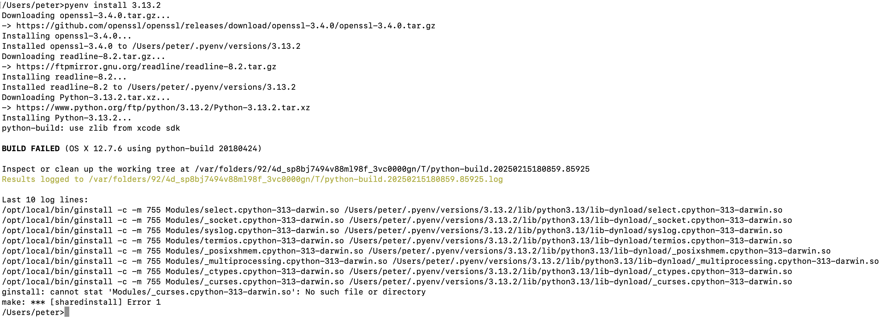
If you are using macports instead of homebrew, you may have this problem. Solved by this: LDFLAGS="-L/opt/local/lib" CPPFLAGS="-I/opt/local/include" pyenv install 3.12.6
run this command
install_name_tool -add_rpath /Library/Developer/CommandLineTools/Library/Frameworks `which nextpnr-ice40`
Edit CMakeLists.txt, add these two line on top
INCLUDE_DIRECTORIES(/opt/local/include)
LINK_DIRECTORIES(/opt/local/lib)
import chisel3._
import chisel3.util._
import _root_.circt.stage.ChiselStage

class MyRam extends Module {
  val io = IO(new Bundle {
    val addr = Input(UInt(8.W))
    val dataIn = Input(UInt(8.W))
    val dataOut = Output(UInt(8.W))
    val write = Input(Bool())
  })

  val symcMem = SyncReadMem(256, UInt(8.W))
  val initDone = RegInit(false.B)

  when(!initDone) {
    io.dataOut := 0.U
    initDone := true.B
  }.otherwise {
    io.dataOut := DontCare // Ensure dataOut is not driven by default
    when(io.write) {
      symcMem.write(io.addr, io.dataIn)
    }.otherwise {
      io.dataOut := symcMem.read(io.addr)
    }
  }
}

object MyMain extends App {
  println(
    ChiselStage.emitSystemVerilog(
      gen = new MyRam,
      firtoolOpts = Array("-disable-all-randomization")
    )
  )
}
import chisel3._
import chisel3.util._
import _root_.circt.stage.ChiselStage

class MyRam extends Module {
  val io = IO(new Bundle {
    val addr = Input(UInt(8.W))
    val dataIn = Input(UInt(8.W))
    val dataOut = Output(UInt(8.W))
    val write = Input(Bool())
  })
  io.dataOut := DontCare

  val symcMem = SyncReadMem(256, UInt(8.W))
  when(io.write) {
    symcMem.write(io.addr, io.dataIn)
  }.otherwise {
    io.dataOut := symcMem.read(io.addr)
  }
}

object MyMain extends App {
  println(
    ChiselStage.emitSystemVerilog(
      gen = new MyRam,
      firtoolOpts = Array("-disable-all-randomization")
    )
  )
}
if you want to send one single byte
this is not working
writer.write(new Int32Array([0x4]).buffer);
this work
writer.write(new Uint8Array([0x4]));
There are two mode in micropython: REPL vs paste mode. I guess the uart of my ESP32 board has no flow control, so you can't send all bytes at once, because it is too fast, so I sleep 100 ms for every 100 bytes.
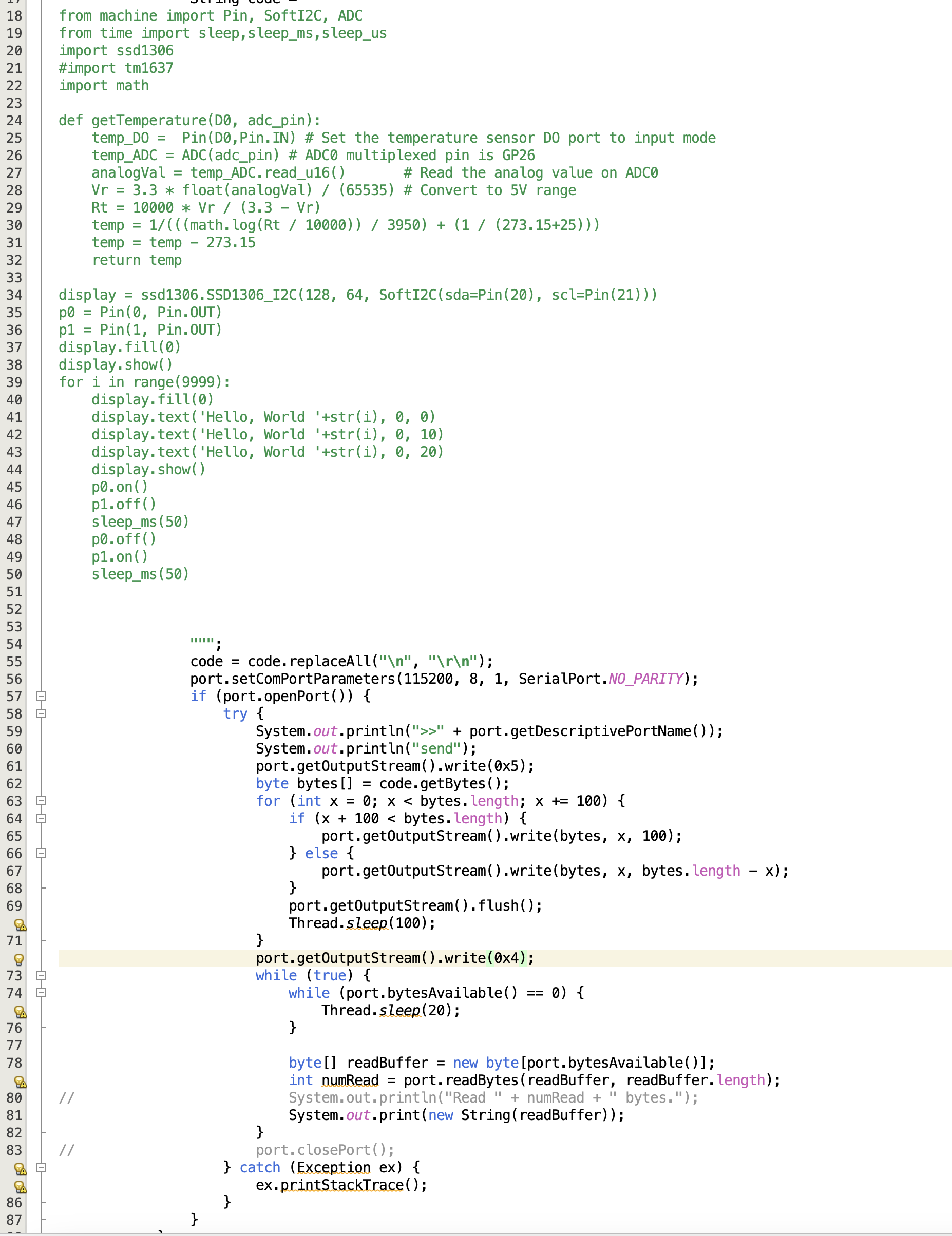
REPL mode
You can't just send your python code, you need to remind two things: the indent and the return of indent. See the below diagram, in line 26 should be one indent but you can't have it, because the line 25 is indent-ed so all next lines are supposed no need to indent again. So you can see from line 26 to 32, there is no indent. Secondly, in line 34, you need \r to return from indent to no-indent

Paste mode
In paste mode, you DON'T have to change anything to your code like the last section. But you need to send 0x5 to enter paste mode and send 0x4 to leave paste mode, after that, the program will run right after it. See line 61 and 72

香港有人係咁,廿幾歲畢業出黎做野,做左幾年對隻language開始熟,佢地唔係鑽落去language下面睇下發生緊乜野,例如啲code點compile呀,debug點做呀咁。佢地會作一出個難以解釋嘅現象,就係跳去另一隻high level language到再玩過,而當佢地玩到興起玩左幾年,佢地再次唔係想知道隻language嘅底層,而係再一次又跳去其它high level language到碌多一次,難道唔想知揸係手裏面把刀係咩黎?我叫呢一種現象做「香港Python仔現象」。舉個例子,2003年班友玩vc++,跟住跳去c#,跟住又跳去java,而家又跳去python。因為咁樣跳法本質上對過去學嘅語言都唔方認識得深,所以如果而家有個阿叔好推崇python,對其它language只停留係誇誇其談攞唔出到戰鬥力,佢大概率係咁。
要改變,就要做好科普,揭露python底層所有野,咁先至有機會改變。但呢班友會唔會變未知。
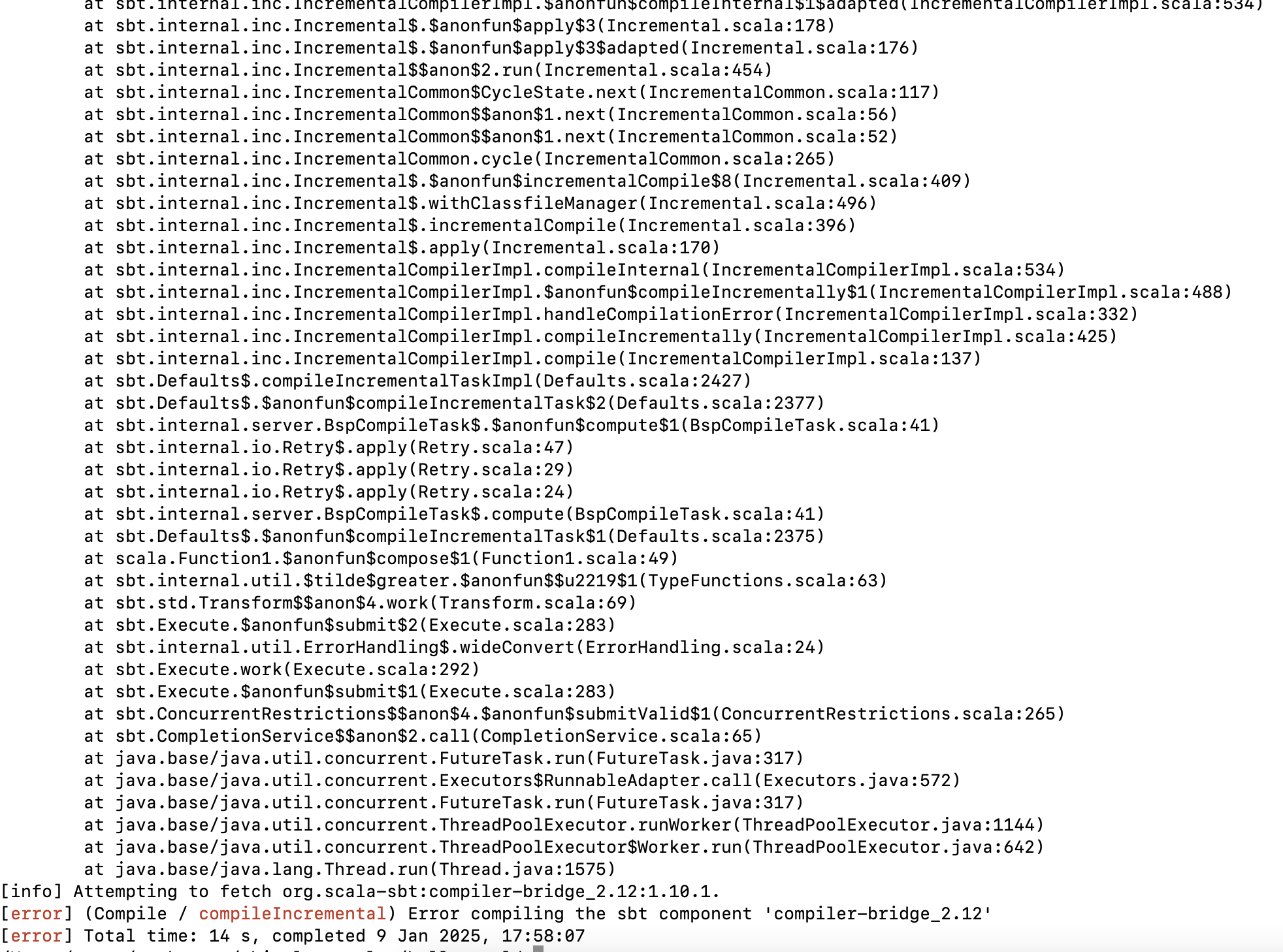
When running the chisel book example, we got Error compiling the sbt component 'compiler-bridge_2.12'. Here are the way to solve it
git clone https://github.com/schoeberl/chisel-examples.git
Edit hello-world/build.sbt
scalaVersion := "2.13.12"

scalacOptions ++= Seq(
  "-feature",
  "-language:reflectiveCalls",
)

// Chisel 3.5
// addCompilerPlugin("edu.berkeley.cs" % "chisel3-plugin" % "6.0.0" cross CrossVersion.full)
// libraryDependencies += "edu.berkeley.cs" %% "chisel3" % "6.0.0"
// libraryDependencies += "edu.berkeley.cs" %% "chiseltest" % "0.6.0"

val chiselVersion = "6.0.0"
addCompilerPlugin("org.chipsalliance" % "chisel-plugin" % chiselVersion cross CrossVersion.full)
libraryDependencies += "org.chipsalliance" %% "chisel" % chiselVersion
libraryDependencies += "edu.berkeley.cs" %% "chiseltest" % "0.6.0" % "test"
Edit hello-world/src/main/scala/Hello.scala
/*
 * This code is a minimal hardware described in Chisel.
 *
 * Blinking LED: the FPGA version of Hello World
 */

import chisel3._
import circt.stage.ChiselStage

/**
 * The blinking LED component.
 */

class Hello extends Module {
  val io = IO(new Bundle {
    val led = Output(UInt(1.W))
  })
  val CNT_MAX = (50000000 / 2 - 1).U

  val cntReg = RegInit(0.U(32.W))
  val blkReg = RegInit(0.U(1.W))

  cntReg := cntReg + 1.U
  when(cntReg === CNT_MAX) {
    cntReg := 0.U
    blkReg := ~blkReg
  }
  io.led := blkReg
}

/**
 * An object extending App to generate the Verilog code.
 */
object Hello extends App {
  println(
    ChiselStage.emitSystemVerilog(
      new Hello(),
      firtoolOpts = Array("-disable-all-randomization", "-strip-debug-info")
    )
  )
}
香港人嘅老土活該沒有科技,我而家分析俾你地睇香港人嘅老土係有幾老土,以及老土嘅香港人點解覺得自己唔老土

第一老土 : 你憑咩
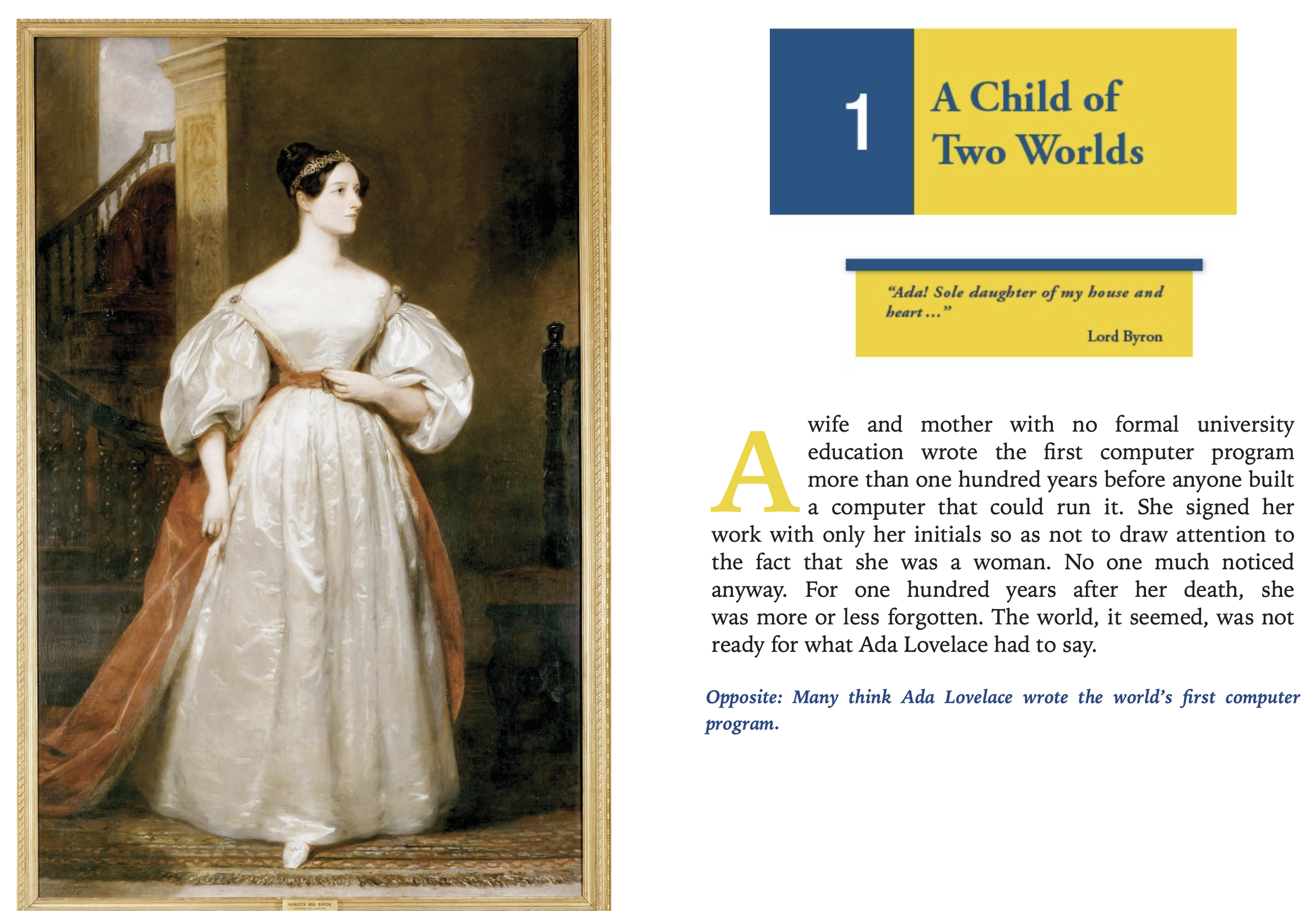
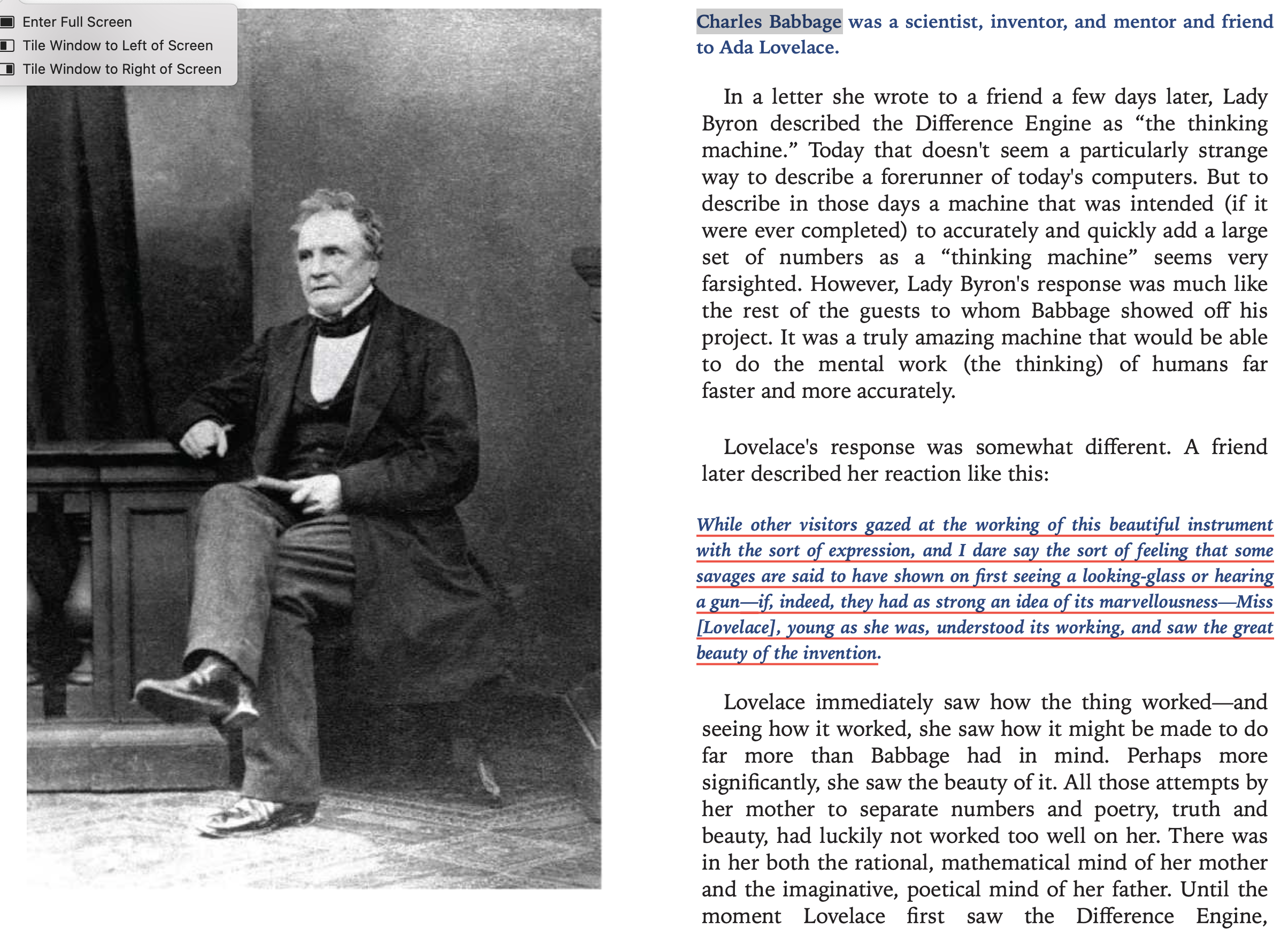
佢地所謂嘅論證不外乎係黎自你所受嘅教育同埋經驗,佢地會話你又唔係哈佛MIT學咩野人搞之類嘅言論,但呢班無讀歷史嘅人唔知好多科學家都係自學為主。(見下圖)
香港人老土在永遠人地努力做,佢地就會問"你憑咩",其實呢一句好無敵,因為當你做緊而又未做完嘅時間你的確無力反駁呢一句,由其是你係做緊一啲你自己都唔知做唔做到嘅野時,你更加無力反駁。但呢班友永遠唔明,科學嘅發現好多時就係意外發現,好多野唔做就唔唔知得唔得,而呢班咁嘅人最叻就係用呢句去質疑你,佢地嘅內心世界就係「嘩,你做呀,你有無諗過㗎」,跟住就會覺得自己好似好有經驗,好似真係以為自己曾經做過咁,知道你條路係唔通,其實個現實就係,呢班友根本無做過,而更深一層嘅就係,佢地連去嘗試嘅基本實力都無,佢地唔係連個for-loop都寫唔出就係技術只夠寫啲script仔,真係可憐。
第二老土 : 話人畫餅
呢個世界唔係所有人都需要理想,而理想呢樣野個實現率必定為低。香港地當然多人畫餅,但係係唔係畫餅好容易分,得個噏字唔做咪就係畫餅囉,會做嘅又點會算係畫餅呢,但係呢班咁嘅人就最叻攻擊啲為理想而行動嘅人。佢地個底其實係數佬,內心世界非常現實,我估計佢地後生嘅時候都曾經有理想,但手料跟唔上人到中年完全無哂動手能力,思想上變得越黎越現實,腦裏面諗一百個可能性去否定執行嘅成功率,不停俾借口自己逃避執行以至完全喪失執行力,佢地係編程上嘅實力只能點評人地寫嘅program,而自己乜都寫唔到。
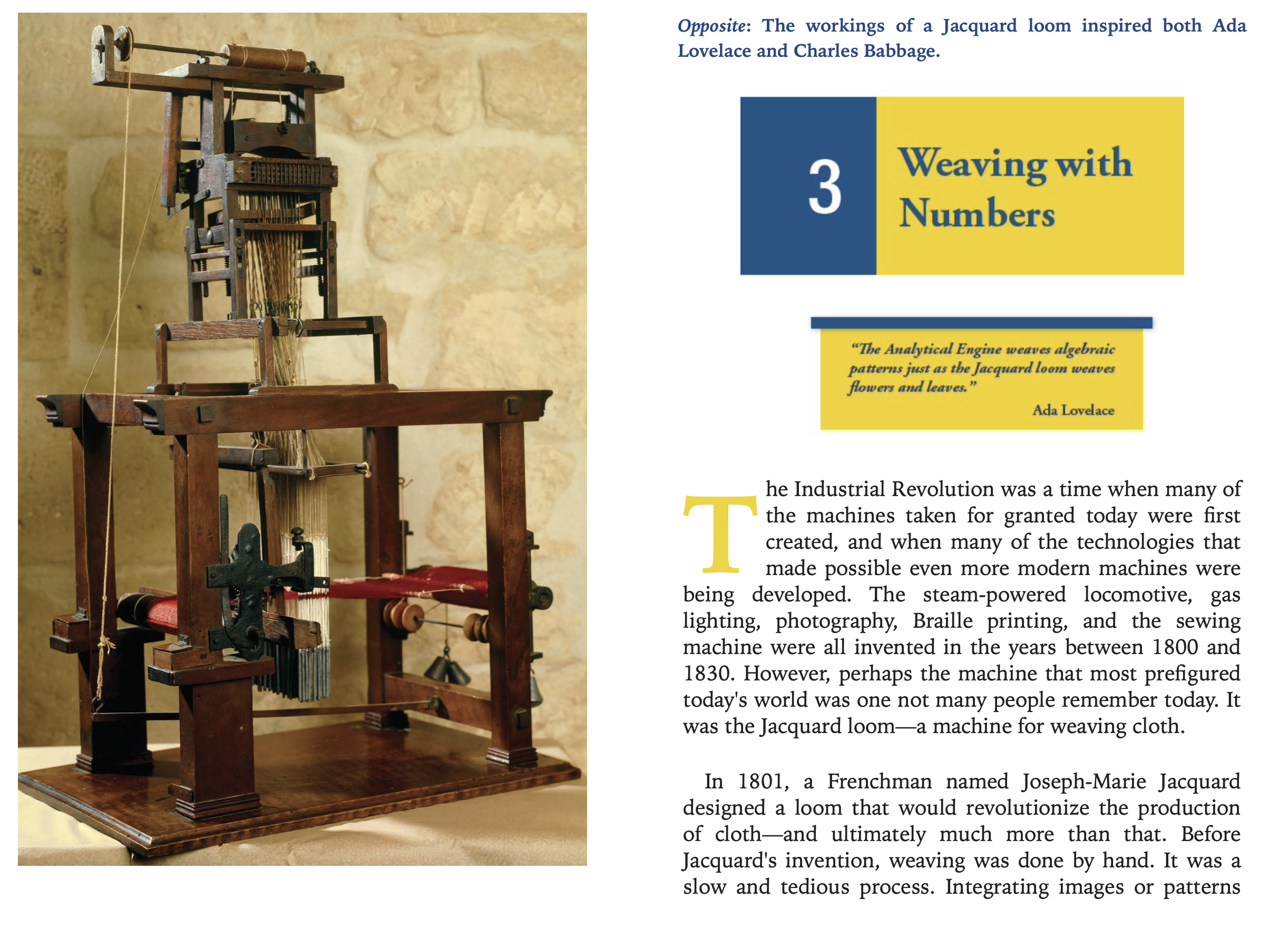
Ada係連電都未係好識運用嘅年代就話要令機器有計算能力,如果香港班友返去佢嗰個時代,呢班友就會話人畫餅。嗰個時代根本就係非常簡陋。當呢班友話人畫餅,佢地嘅內心有一種好充盈嘅感覺,佢地會覺得:「嘿嘿,我真係叻,無俾你利用到」。但係個現實係咩呢,就係呢班友手料根本連俾人利用嘅資格都無,同你講下理想只係發下噏瘋而矣,唔好諗得自己咁有料可以俾人利用。
第三老土:話做唔做或者揾借口唔繼續做
話做唔做嘅人主要會話你唔夠條件做,做緊又揾借口唔繼續做嘅人會話發現你原來唔夠料做,又或者話發現你身上有啲缺點而唔再同你合作做。總之無論係咩原因都好,結果就係唔做。我地睇返Ada Lovelace個Case,當佢話要做一部Thinking machine嘅時候,佢mentor Charles Babbage唔會因為佢太天馬行空而屈佢畫餅,想反地會動手一齊做。而Charles Babbage亦都唔會話Ada無足夠嘅錢同埋未讀過大學就話人無料而做做下唔做。
https://conorfennell.github.io/scala-zen/articles/sbt.html
sbt "tasks -v"
  bgRun                           Start an application's default main class as a background job
  bgRunMain                       Start a provided main class as a background job
  clean                           Deletes files produced by the build, such as generated sources, compiled classes, and task caches.
  compile                         Compiles sources.
  console                         Starts the Scala interpreter with the project classes on the classpath.
  consoleProject                  Starts the Scala interpreter with the sbt and the build definition on the classpath and useful imports.
  consoleQuick                    Starts the Scala interpreter with the project dependencies on the classpath.
  copyResources                   Copies resources to the output directory.
  deliver                         Generates the Ivy file for publishing to a repository.
  deliverLocal                    Generates the Ivy file for publishing to the local repository.
  dependencyClasspath             The classpath consisting of internal and external, managed and unmanaged dependencies.
  dependencyClasspathAsJars       The classpath consisting of internal and external, managed and unmanaged dependencies, all as JARs.
  doc                             Generates API documentation.
  exportedProductJars             Build products that go on the exported classpath as JARs.
  exportedProductJarsIfMissing    Build products that go on the exported classpath as JARs if missing.
  exportedProductJarsNoTracking   Just the exported classpath as JARs without triggering the compilation.
  fullClasspath                   The exported classpath, consisting of build products and unmanaged and managed, internal and external dependencies.
  fullClasspathAsJars             The exported classpath, consisting of build products and unmanaged and managed, internal and external dependencies, all as JARs.
  internalDependencyAsJars        The internal (inter-project) classpath as JARs.
  javaOptions                     Options passed to a new JVM when forking.
  javacOptions                    Options for the Java compiler.
  mainClass                       Defines the main class for packaging or running.
  makePom                         Generates a pom for publishing when publishing Maven-style.
  manipulateBytecode              Manipulates generated bytecode
  mappings                        Defines the mappings from a file to a path, used by packaging, for example.
  package                         Produces the main artifact, such as a binary jar.  This is typically an alias for the task that actually does the packaging.
  packageBin                      Produces a main artifact, such as a binary jar.
  packageDoc                      Produces a documentation artifact, such as a jar containing API documentation.
  packageSrc                      Produces a source artifact, such as a jar containing sources and resources.
  printWarnings                   Shows warnings from compilation, including ones that weren't printed initially.
  publish                         Publishes artifacts to a repository.
  publishLocal                    Publishes artifacts to the local Ivy repository.
  publishM2                       Publishes artifacts to the local Maven repository.
  publishTo                       The resolver to publish to.
  publisher                       Provides the sbt interface to publisher
  run                             Runs a main class, passing along arguments provided on the command line.
  runMain                         Runs the main class selected by the first argument, passing the remaining arguments to the main method.
  scalacOptions                   Options for the Scala compiler.
  test                            Executes all tests.
  testOnly                        Executes the tests provided as arguments or all tests if no arguments are provided.
  testOptions                     Options for running tests.
  testQuick                       Executes the tests that either failed before, were not run or whose transitive dependencies changed, among those provided as arguments.
  unmanagedClasspath              Classpath entries (deep) that are manually managed.
  unmanagedJars                   Classpath entries for the current project (shallow) that are manually managed.
  unmanagedResources              Unmanaged resources, which are manually created.
  unmanagedSources                Unmanaged sources, which are manually created.
  update                          Resolves and optionally retrieves dependencies, producing a report.
  updateClassifiers               Resolves and optionally retrieves classified artifacts, such as javadocs and sources, for dependency definitions, transitively.
  updateSbtClassifiers            Resolves and optionally retrieves classifiers, such as javadocs and sources, for sbt, transitively.
  woo                             Woo